M–46
REAR DRIVE SHAFT
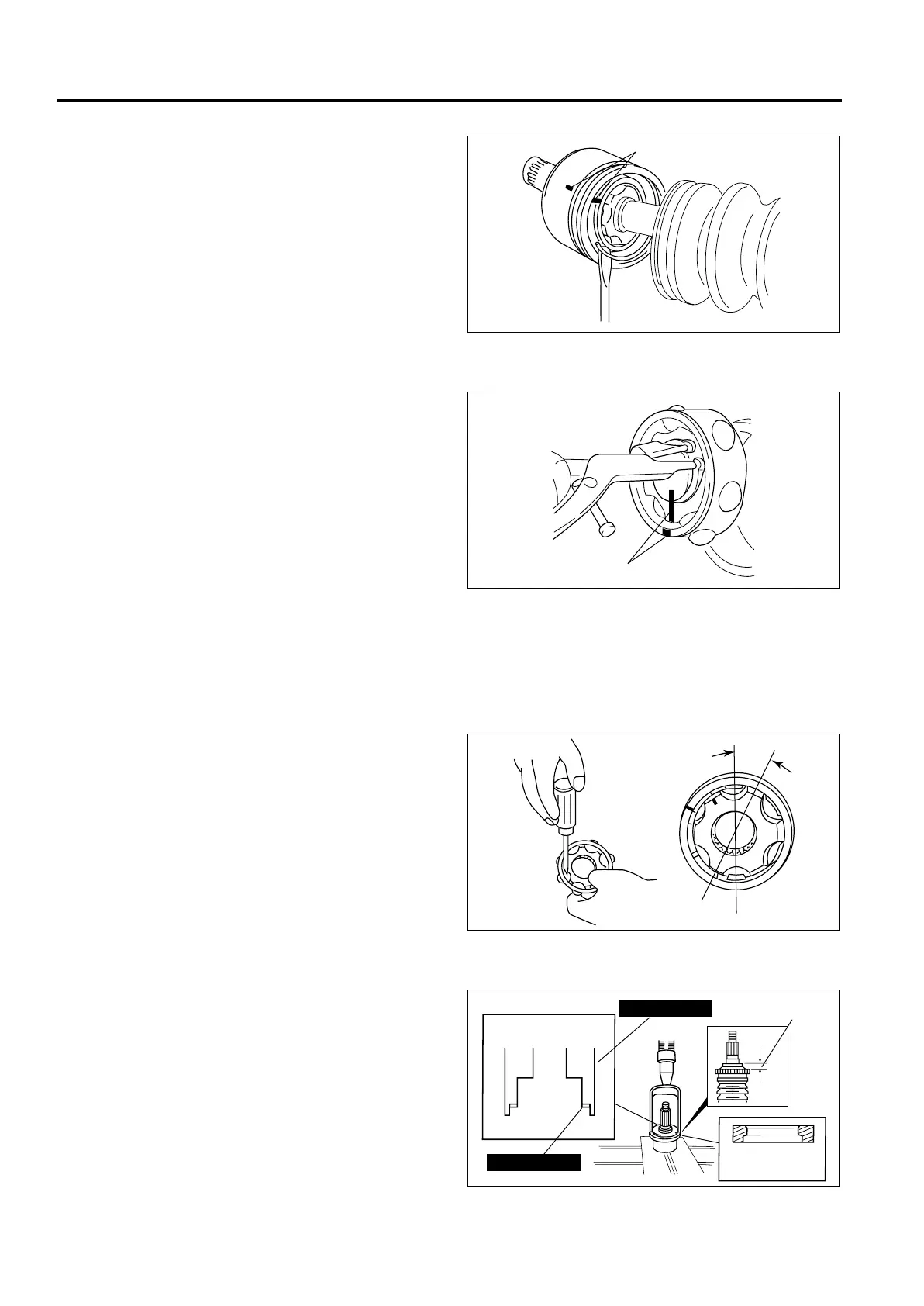
Clip Disassembly Note
1. Mark the drive shaft and outer ring for proper
assembly.
Caution
• Mark with paint; do not use a punch.
2. Remove the clip.
Snap Ring Disassembly Note
1. Mark the drive shaft end and inner ring for proper
reassembly.
Caution
• Mark with paint; do not use a punch.
2. Remove the snap ring using snap-ring pliers.
Balls, Inner Ring, Cage Disassembly Note
1. Mark the inner ring and cage for proper reassembly.
Caution
• Mark with paint; do not use a punch.
2. Turn the cage approximately 30 degrees and
pull the cage and balls from the inner ring.
ABS Sensor Rotor Assembly Note
1. Install the ABS sensor rotor to the drive shaft
using the SSTs.
MARK
A6E6316W010
MARK
A6E63172005
30°
A6J63172006
49 B025 006A
20.7 mm
{0.81 in}
49 B025 009A
ABS SENSOR
ROTOR
A6E63172008












 To Next Page