M–60
REAR DIFFERENTIAL
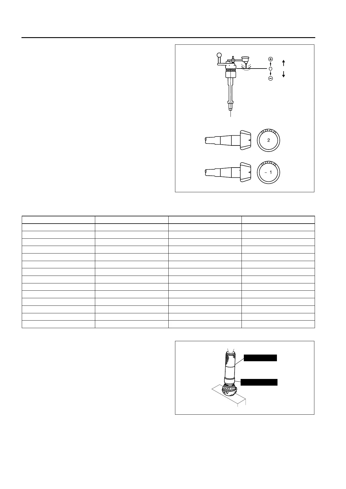
9. Add the two (left and right) values obtained by the
measurements taken in Step 8 and then divide
the total by 2. From this result, subtract the result
obtained by dividing the number inscribed on the
end surface of the drive pinion by 100. (If there is
no figure inscribed, use 0.) This is the pinion
height adjustment value.
Pinion height
–0.025—0.025 mm {–0.001—0.001 in}
Note
• For example, the measured results obtained
at Step 8 and 9 are 0.06 mm {0.003 in} and
0.04 mm {0.002 in}, and the figure inscribed
on the end of the drive pinion is 2:
((0.06 mm {0.003 in}+ 0.04 mm {0.002 in}) /
2) – (2/100) = 0.03 mm {0.001 in} (pinion
height adjustment value)
Replace with a spacer 0.03 mm {0.001 in}
thicker than the currently used one. Spacer
thickness is set at 0.015 mm {0.0006 in}
increments, therefore select the closest
spacer thickness and assemble.
• Install the spacer with the chamfer on the
SST side.
Spacer thickness
10. Assemble the spacer selected for the pinion height adjustment to the drive pinion.
11. Press the bearing inner race (rear bearing) into
the drive pinion using the SSTs and a press.
A6A63192028
Identification mark Thickness (mm {in}) Identification mark Thickness (mm {in})
08 3.08 {0.1213} 29 3.29 {0.1295}
09 3.095 {0.1219} 30 3.305 {0.1301}
11 3.11 {0.1224} 32 3.32 {0.1307}
12 3.125 {0.1230} 33 3.335 {0.1313}
14 3.14 {0.1236} 35 3.35 {0.1319}
15 3.155 {0.1242} 36 3.365 {0.1325}
17 3.17 {0.1248} 38 3.38 {0.1331}
18 3.185 {0.1254} 39 3.395 {0.1337}
20 3.20 {0.1260} 41 3.41 {0.1343}
21 3.215 {0.1266} 42 3.425 {0.1348}
23 3.23 {0.1272} 44 3.44 {0.1354}
24 3.245 {0.1278} 45 3.455 {0.1360}
26 3.26 {0.1283} 47 3.47 {0.1366}
27 3.275 {0.1289} ——
49 F401 331
49 F401 337A
A6A63192029
 Loading...