N–12
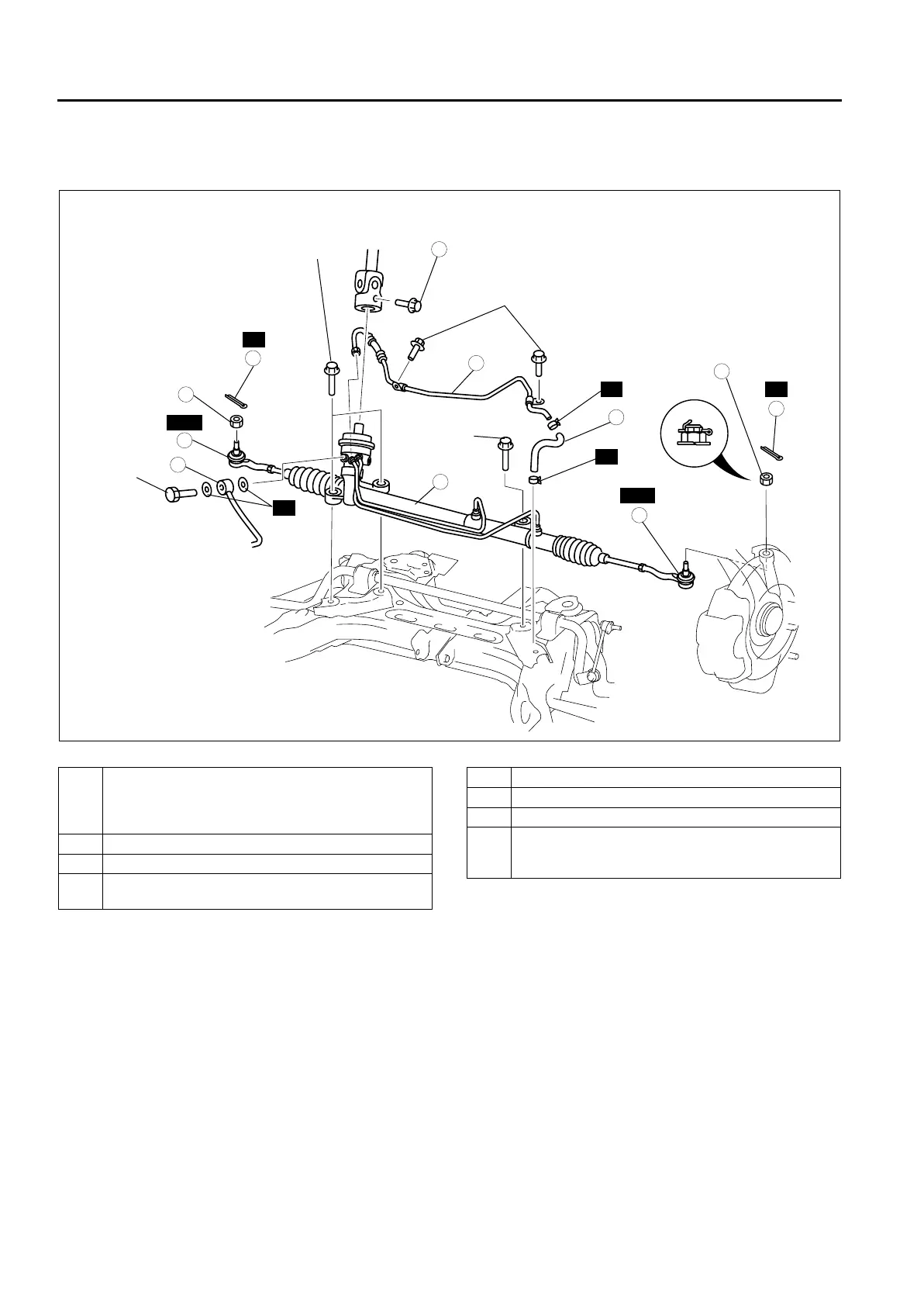
ENGINE SPEED SENSING POWER STEERING
R.H.D.
1. Remove in the order indicated in the table.
2. Install in the reverse order of removal.
3. After installation, inspect the toe-in.
.
End Of Sie
4
5
4
3
3
6
2
2
SST
SST
R
R
R
1
8
74.4—104.8
{7.6—10.6,
54.9—77.2}
18.6—26.5
{1.9—2.7,
13.8—19.5}
7.8—10.8
{0.8—1.1,
5.8—7.9}
33.0—44.1
{3.3—4.4,
21.7—32.5}
74.4—104.8
{7.6—10.6,
54.9—77.23}
33.0—44.1
{3.3—4.4,
21.7—32.5}
29.4—44.1
{3.0—4.4,
21.7—32.5}
7
R
R
A6E66142004
1 Bolt (intermediate shaft)
(See N–10 Bolt (intermediate shaft) removal note)
(See N–11 Bolt (intermediate shaft) installation
note)
2 Cotter pin
3Nut
4 Tie-rod end ball joint
(See N–10 Tie-rod end ball joint removal note)
5 Pressure pipe
6 Return hose
7 Return pipe
8 Steering gear and linkage
(See N–11 Steering gear and linkage installation
note)