P–28
ON-BOARD DIAGNOSTIC
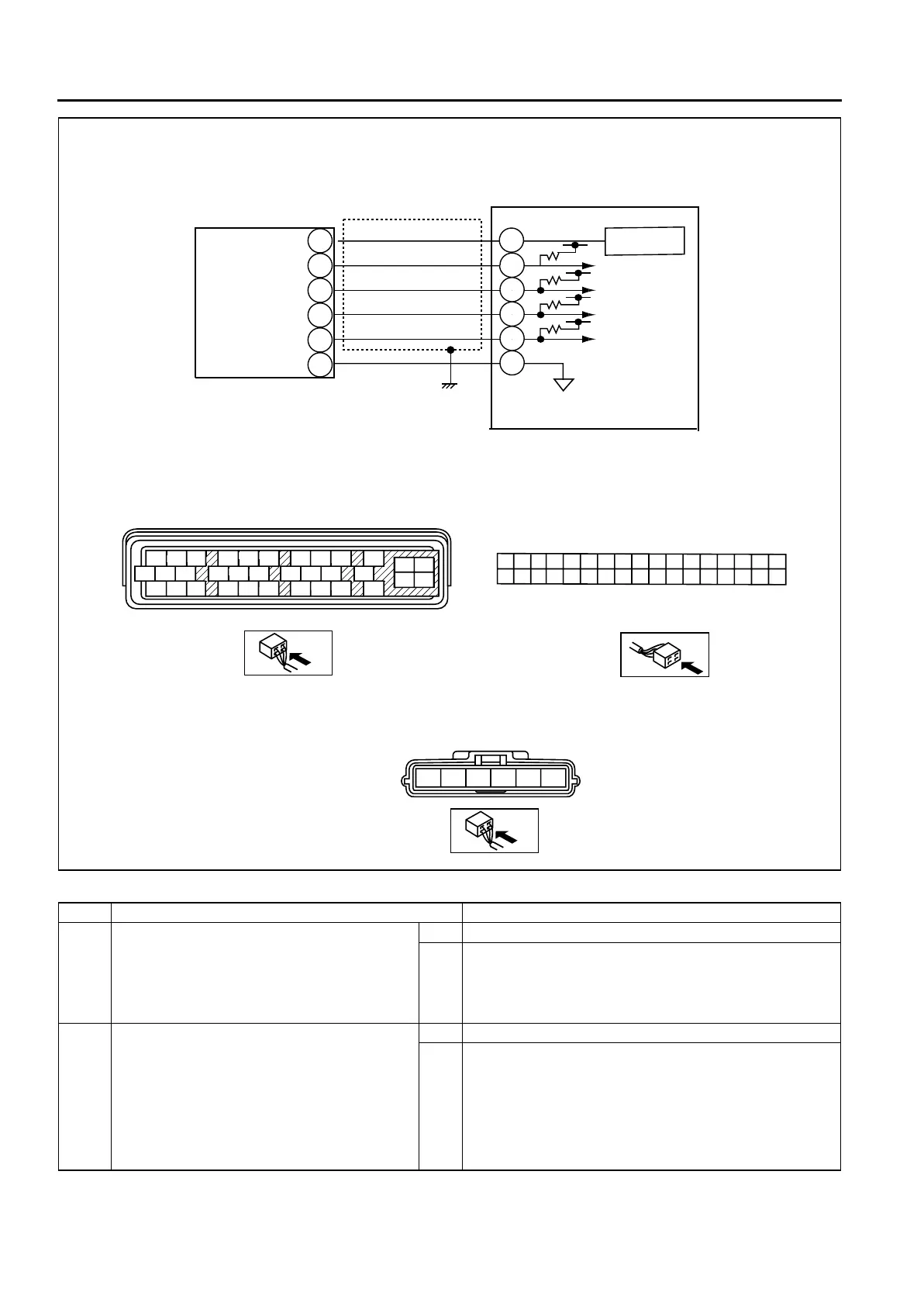
Diagnostic procedure
STEP INSPECTION ACTION
1 INSPECT COMBINE SENSOR POWER
SUPPLY CIRCUIT FOR OPEN CIRCUIT
• Turn ignition key to ON (engine OFF).
• Measure voltage between combine sensor
terminal C (harness side) and ground.
• Is voltage 4.5—5.5 V?
Yes Go to next step.
No Repair or replace harness for open circuit between combine
sensor terminal C and ignition switch, then go to Step 8.
2 INSPECT COMBINE SENSOR GROUND
CIRCUIT FOR OPEN CIRCUIT
• Turn ignition key to OFF.
• Disconnect DSC HU/CM and combine
sensor connectors.
• Inspect continuity between DSC HU/CM
terminal Y (harness side) and combine
sensor terminal E (harness side).
• Is there continuity?
Yes Go to next step.
No Repair or replace harness for open circuit between DSC
HU/CM terminal Y and combine sensor terminal E, then go
to Step 8.
SST (49 G066 004)
A
Q
B
C
DE
F
G
H
I
J
DSC HU/CM HARNESS SIDE CONNECTOR
A
C
E
H
K
NQ
T
W
ZAC
AF
FILORU
X
AA
AD
AG
G
J
M
PS
V
Y
AB
AE
AH
B
D
KN
T
WZ
AC
AF
LO
RU
X
AA
AD
AG
MP
S
V
Y
AB
AE
AH
5V
REGULATOR
COMBINE SENSOR
F
ABCDE
COMBINE SENSOR HARNESS
SIDE CONNECTOR
C
F
D
A
B
E
P
S
T
V
O
Y
DSC HU/CM