U–16
CONTROL SYSTEM
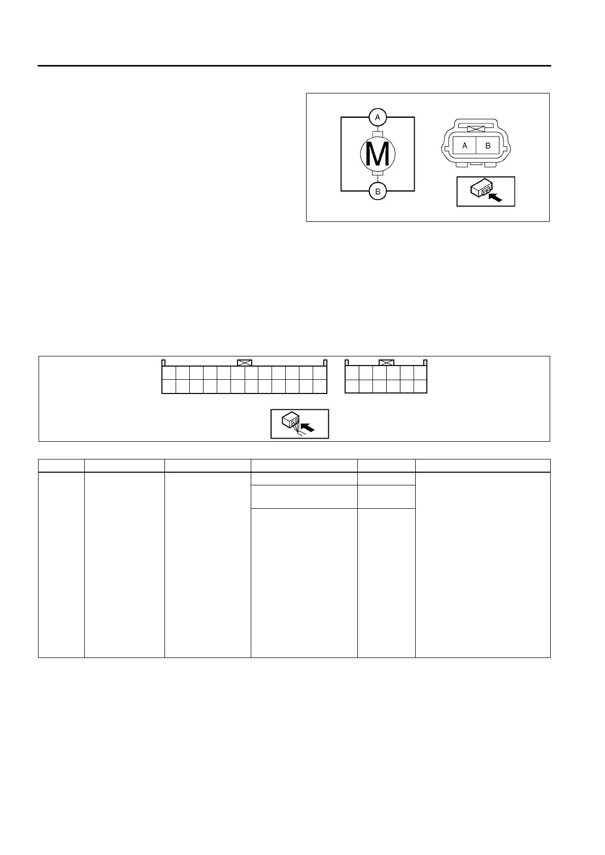
FUEL PUMP (WATER HEATER SYSTEM) INSPECTION
A6E854013350201
1. Inspect for continuity between fuel pump terminal
A and B using an ohmmeter.
• If not as specified, replace the fuel pump
(water heater system).
End Of Sie
CLIMATE CONTROL UNIT INSPECTION
A6E854061190201
Full-auto Air Conditioner
1. Connect the all center panel connectors.
2. Turn the ignition switch to ON position.
3. Measure the voltage at each climate control unit terminal and refer to the terminal voltage list.
• If not as specified, inspect the parts listed under “Action” and the related wiring harness.
— If there is any malfunction, replace the climate control unit.
Terminal Voltage List (Reference)
AME8540W007
Terminal Signal Connected to Test condition Voltage (V) Action
1A Blower motor
feedback signal
• Blower motor
• Power MOS
FET
Fan switch is OFF 12 1. Inspect for continuity or
short circuit (Climate control
unit—blower motor: 1A—B)
(Climate control unit—power
MOS FET: 1A—B, 1C—E)
(Blower motor—blower
relay: A—C) (Blower relay—
fuse: D—BLOWER 40 A
fuse)
2. Inspect for continuity (Power
MOS FET—ground: A—
GND) (Blower relay—
ground: A—GND)
3. Inspect power MOS FET
4. Inspect blower motor
5. Inspect blower relay
6. Inspect BLOWER 40 A fuse
7. Replace power MOS FET
Fan switch is at manual
LO
7.8
Fan switch is at manual
HI
0.2
2A
1W
2B
2C
2D
2E
2F
2G
2H
2I
2K
2L
*
1A
1B
*
*
*
*
*
1X
1C
1E
1F
*
1I
1K
1M
1O
1P
1Q
1S
1T
1U
1J1L
A6E85402001
 Loading...