2 Design
2 - 40
High-function General-purpose Inverter 3G3RX-V1 User’s Manual (I578-E1)
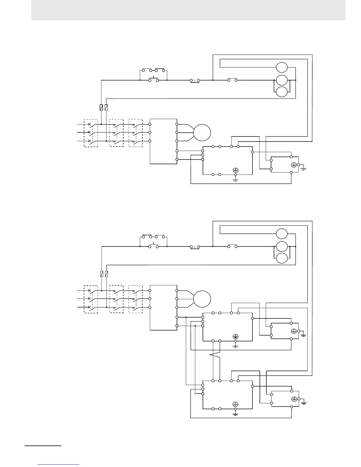
• Wiring diagram for connecting one Regenerative Braking Unit (Model: 3G3AX-RBU23)
• Wiring diagram for connecting two Regenerative Braking Units (Model: 3G3AX-RBU23)
Inverter
Fuse
Motor
P
P
N
SL1 SL2 AL1 AL2
RB
MA1 MA2
3G3AX-RBU23
Master
ON
OFF
RY
RY
MC1
*1
R/L1
S/L2
T/L3
U/T1
V/T2
W/T3
P/+2
N/–
3-phase 200 V
1(AL1)
2(AL2)
P
RB
3G3AX-RBA
/RBB/RBC
MC1
MC2
MC2
*1. For RY, select the contact rating according to the ratings of the coils MC1 and MC2.
*2. MC1 and MC2 are used not only to provide redundancy, but also to meet safety standards.
MC1
MCCB
MC2
R
S
T
*2
Regenerative braking unit
Inverter
Fuse
Motor
P
P
N
SL1 SL2 AL1 AL2
RB
MA1 MA2
3G3AX-RBU23
Master
P
P
N
SL1 SL2 AL1 AL2
RB
MA1 MA2
3G3AX-RBU23
Slave*3
ON
OFF
RY
RY
MC1
*1
R/L1
S/L2
T/L3
U/T1
V/T2
W/T3
P/+2
N/–
1(AL1)
2(AL2)
P
RB
3G3AX-RBA
/RBB/RBC
1(AL1)
2(AL2)
P
RB
3G3AX-RBA
/RBB/RBC
MC1
MC2
MC2
Regenerative braking unit
Regenerative braking unit
*1. For RY, select the contact rating according to the ratings of the coils MC1 and MC2.
*2. MC1 and MC2 are used not only to provide redundancy, but also to meet safety standards.
*3. You need to set DIP switch to regenerative braking unit as a slave, and wire terminal SL1 and SL2.
3-phase 200 V
MC1
MCCB
MC2
R
S
T
*2
 Loading...


