2 - 41
2 Design
High-function General-purpose Inverter 3G3RX-V1 User’s Manual (I578-E1)
2-3 Wiring
2
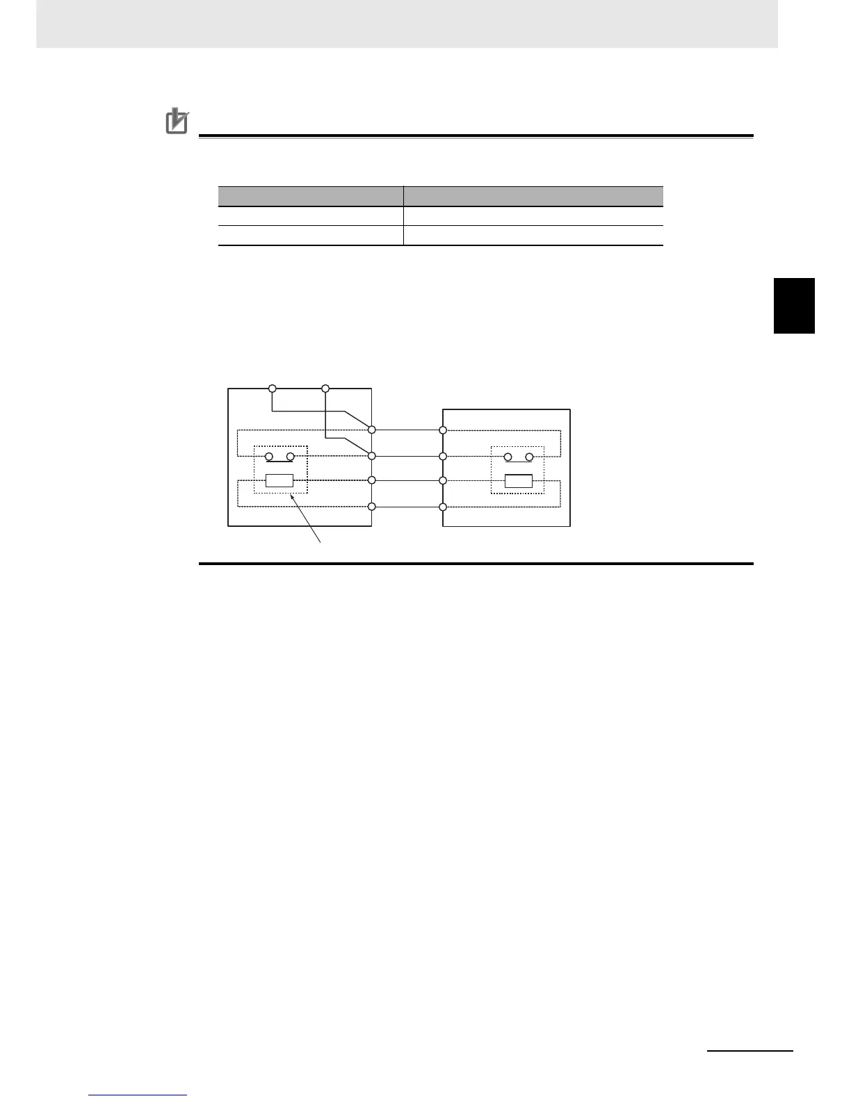
2-3-4 Wiring for Main Circuit Terminals
• Each braking resistor has alarm contact (thermal relay output) terminals as shown below. Be
sure to perform wiring for these terminals.
• To remove the built-in register from the Regenerative Braking Unit Built-in Braking Resister
(Model: 3G3AX-RBU21/RBU22/RBU41) in order to use the Braking Resistor (Model:
3G3AX-RBA/RBB/RBC), remove the wiring of thermal relay for the built-in resistor and
connect the alarm contact (thermal relay output) terminals of the braking resistor with the
terminals R1 and R2.
Model Alarm contact terminals
3G3AX-RBA/RBB Between terminal 1 and terminal 2
3G3AX-RBC Between terminal AL1 and terminal AL2
AL1 AL2
R1
R2
Regenerative braking unit built-in braking resister
(Model: 3G3AX-RBU21/RBU22/RBU41)
Remove the built-in register.
Resistor
P
RB
Resistor
1(AL1)
2(AL2)
P
RB
External braking resistor
(Model: 3G3AX-RBA/RBB/RBC)
 Loading...


