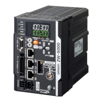
Part Names and Functions
ZW-7000/5000
User's Manual
2
Installation and Connections
47
l Connectors/terminals
Rear view
Bottom view
No. Names Functions
21 RS-232C connector Connect the RS-232C cable when you are connecting the system with a PLC or personal
computer through RS-232C.
For the RS-232C cable, please use the following exclusive products:
If you use a cable not included in the exclusiv
e
products, a false operation or breakdown
may result.
• For connecting to a PLC or programmable terminal: ZW-XPT2
• For connecting to a PC: ZW-XRS2
22 Ethernet connector This connector is used to connect with a personal computer through Ethernet.
For Ethernet cable, use a commercially available cable which satisfies the following condi-
tions:
• Category: 5e, or higher and Length: 30m or shorter.
• RJ45 connector (8 pin registered jack)
• When connect 1:1: select Ethernet crossover cable.
• When connect by network HUB: select straight cable.
23 EtherCAT input connector This connector is used to connect to EtherCAT-compatible devices.
Use the recommended EtherCAT cable.
24 EtherCAT input output connector This connector is used to connect to EtherCAT-compatible devices.
Use the recommended EtherCAT cable.
25 24 V input terminal block This connector is used to connect to Sensor Controller DC24 V power supply. The length
of Cables should be less than 30 m.
26 32-pole extension connector • This connector connects the following output and input signals:
• Output signal:
Parallel I/Os, including output for judgment, ALARM, BUSY
ENABLE, Bank Number, SYNCFLG/TRIGBUSY, STABILITY,
LO G S TAT, LO G E RR , TA SKS TAT
• Input signal:
ZERO, RESET, TIMING, LIGHT OFF, LOGGING,
Bank Number, SYNC/TRIG
• Make sure to use the electric cable within 2m.
27 Analog output terminal block This connector connects the output for analog voltage and analog current.
Use the electric cable within 2m.
28 Fiber adapter The fiber adapter connects the fiber connector.
29 ROM connector The ROM connector connects the calibration ROM.
30 Frame ground terminal This is the connector for frame ground. It connects grounding wire.
No. Names Functions
31 DIN track attachment hook Used when fixing the Sensor Controller on DIN track.
No. Names Functions
32 Installation screw hole Used when fixing the Sensor Controller with screws.

 Loading...