Troubleshooting
ZW-7000/5000
User's Manual
255
8
Troubleshooting
8-2 Troubleshooting
This section describes how to temporarily remedy hardware-related trouble.
Check the items below before sending the hardware for repair.
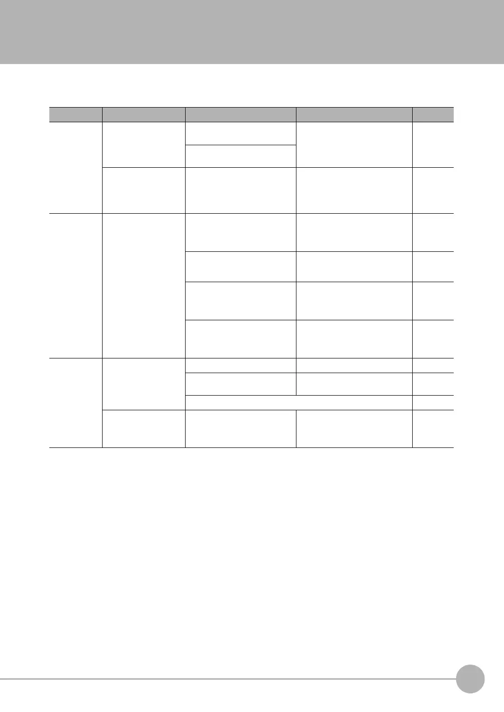
Error type Phenomenon Cause Countermeasure Pages
Startup error Device restarts during
operat
ion.
The power supply device is not
connected correctly.
Check if the power supply device
conforms to the power supply
specifications.
p.6
The power supply capacity is
i
nsufficien
t.
[NO.ROM] is displayed on
the ma
in digital.
The calibration ROM is not
connected.
Connect the calibration ROM.
If the Calibration ROM is lost, or it
fails, per
form the temporary solution
indicated on p.174 and then contact
your OMRON representative.
p.26
Sensor Head
cal
ibr
ation error
Sensor Head calibration
fails.
The connection between the
Sensor Controller and the Sensor
Head or the extension fiber cable is
not normal.
Confirm that the Sensor Controller,
Sensor
Head, and extension fiber
cable are connected correctly.
p.56
Foreign matter is adhering to the
f
ibe
r cable end surface.
Clean the Sensor Controller, Sensor
Head, and end surface of the
extension fiber cable connector.
p.60
The extension fiber cable is not set
p
rope
rly.
Confirm that the set length of the
extension fiber cable matches the
length of the connected extension
fiber cable.
p.247
The fiber cable is disconnected. The Sensor Head and extension fiber
ca
bl
e need to be replaced or
repaired. Please contact an OMRON
branch or sales office.
−
Display error The main display remains
on “- - - - - -.”
TIMING input is not ON. Turn the TIMING input ON. p.69
The trigger level is not
approp
riately set for self-trigger.
Set the self-trigger level to an
appropriate value.
p.147
p.226
Refer to the section of "[DARK] is displayed on the main digital.".
−
The main display
becomes “SYSERR.”
A system error has occurred. Identify the cause of the error based
on the error code displayed on the
sub-display and take an appropriate
action.
*1

 Loading...


