Setting Sensing
122
ZW-7000/5000
User's Manual
Setting the Measurement Area
Setting the start and end positions of the measurement area and mask area on the selected measurement
area allows the area used for measurement to be limited.
Cutting out the areas where there is no measurement object makes it possible to measure the object with
st
abili
ty.
When the measurement object is set to “Glass,” measurement may not be performed correctly as
measu
rement
will be influenced by reflection from the rear surface. If this happens, set the measurement area
of each measurement surface so that they can be correctly measured.
The measurement area can be set by dragging the start axis and end axis displayed on the sensing monitor
screen.
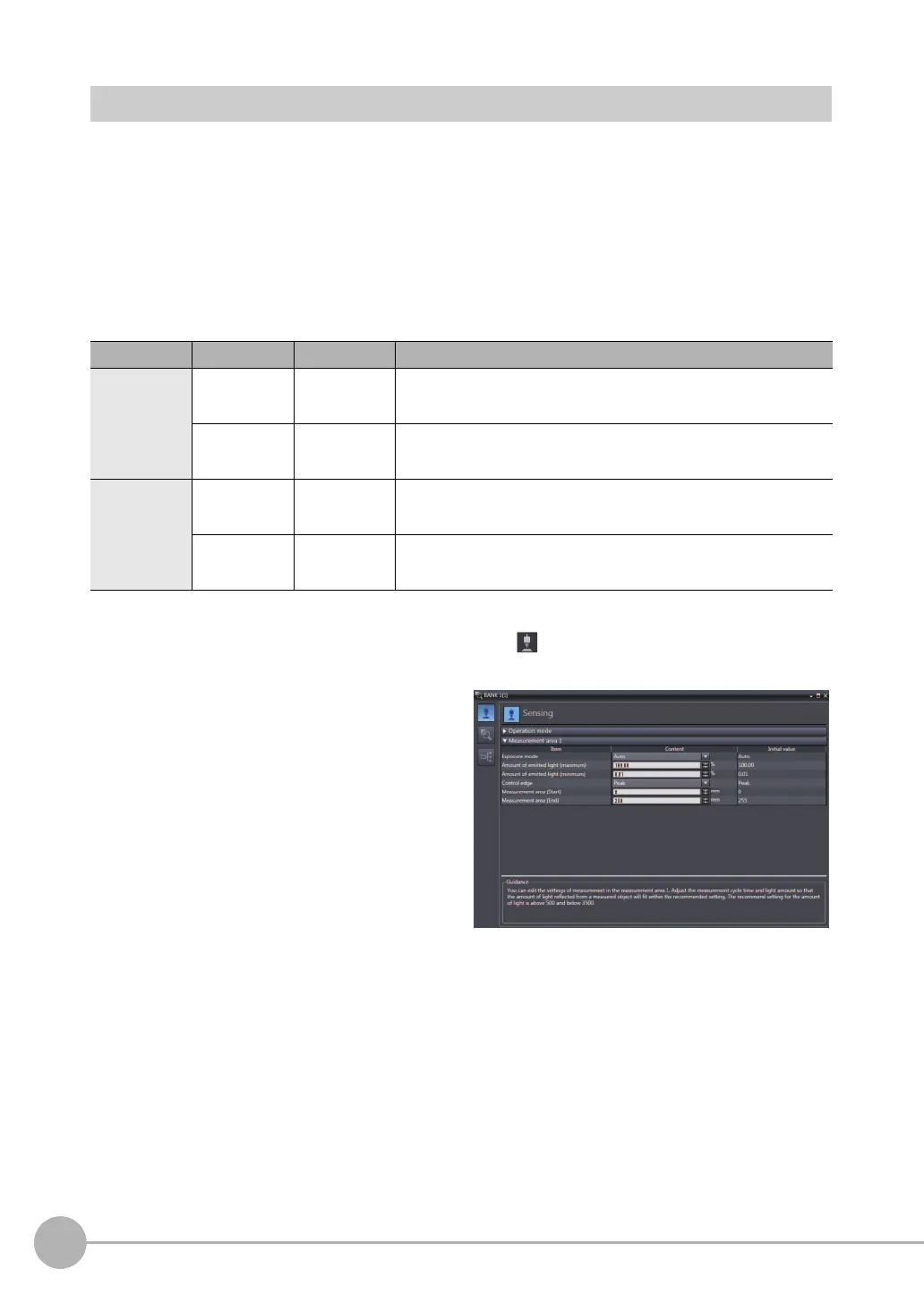
Multiviewer Explore : [Bank] | [(Bank Data Name)] (double click)
→ Edit pane : [Sensing setting] icon ( )
→ Sensing settings window : [Measurement area 1]
Item Setting item Setting value Description
Measurement
area 1
Measurement
area (start)
Measuring range
of Sensor Head
[mm]
Set the measurement start position for the selected measurement area.
When the window for the selected measurement area is open, the start
position can also be edited
by dragging the start line on the line bright monitor.
Measurement
area (end)
Measuring r
ange
of Sensor Head
[mm]
Set the measurement end position for the selected measurement area.
When the window for the selected measurement area is open, the end
position can also be edited by dragging the end line on the line bright monitor.
Measurement
area 2
* Only in the 2
area mode
Measureme
nt
area (st
ar
t)
Measuring range
of Sensor Head
[mm]
Set the measurement start position for the selected measurement area 2.
When the window for the selected measurement area is open, the start
position can also be edited by dragging the start line on the line bright monitor
Measurement
area (end)
Measuring r
ange
of Sensor Head
[mm]
Set the measurement end position for the selected measurement area 2.
When the window for the selected measurement area is open, the end
position can also be edited by dragging the end line on the line bright monitor.
1
Set the values of [Measurement area (start)]
and [Measurement area (end)].

 Loading...


