2
Installation and Connections
Installation
ZW-7000/5000
User's Manual
49
2-3 Installation
Installation of Sensor Head
Installation procedure
• For the location screw holes, see the external dimensions.
• Adjust settings while visually checking the position and brigh
tness of a spot on an object with diffuse reflection.
When measuring on a high-reflectivity object, such as a mirror or w
afer, visual check may be difficult.
Additionally, the measurement value which set out of the measurement region ma
y be output.
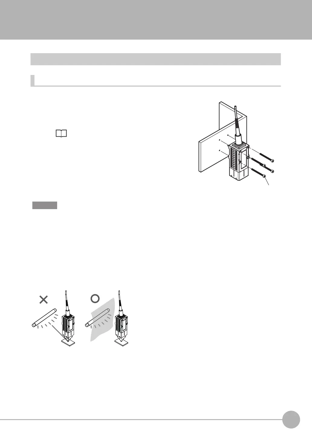
Basic precautions for installation
Do not install the Sensor Head in a place where strong light hits the laser emitter/receiver section of the Sensor
Head. Also, if an object has a shiny surface, the light from the lighting will be reflected and a malfunction may
occur. In such a case, prevent reflection by, for example, covering the light to stop reflection.
1
Place the Sensor Head with an appropriate distance from
the target to measure, fixing it by tightening four M3 screw
inserted into their respective installation holes.
Tightening torque: 0.54 N • m
9-1 Specifications and External Dimensions p.260
Important

 Loading...


