EasyManuals Logo

Omron ZW-7000 Series User Manual

Omron ZW-7000 Series
290 pages
To Next Page IconTo Next Page
To Previous Page IconTo Previous Page
Page #71 background imageLoading...
Page #71 background image
2
Installation and Connections
Wiring
ZW-7000/5000
User's Manual
69
2-4 Wiring
32-pole extension connector
Used for judgment output, control input, etc.
Compatible connector: FX2B series (Hirose Electric Co., Ltd.)
A parallel cable (ZW-XCP2E) for an extension connector with 2 m cable is included.
Cut the unnecessary signal lines so that they do not touch other signal lines.
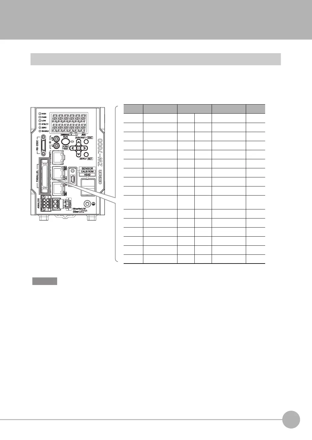
*1 Indicates ZW-XCP2E code color
Color
(*1 )
Signal name No.
(*2 )
Signal name Color
(*1 )
Blue COM_IN1 B16 A16 COM_IN2 Blue
Green TIMING B15 A15 SYNC/TRIG Green
Yellow RESET B14 A14 NC Yellow
Orange ZERO B13 A13 NC Orange
Red LIGHT OFF B12 A12 NC Red
Brown COM_OUT1 B11 A11 COM_OUT3 Brown
Black HIGH B10 A10 STABILITY Black
White PASS B9 A9 LOGERR White
Gray LOW B8 A8 LOGSTAT Gray
Purple ALARM B7 A7 SYNCFLG/
TRIGBUSY
Purple
Blue BUSY B6 A6 TASKSTAT Blue
Green ENABLE B5 A5 COM_IN3 Green
Yellow COM_OUT2 B4 A4 BANK_SEL1 Yellow
Orange BANK_OUT1 B3 A3 BANK_SEL2 Orange
Red BANK_OUT2 B2 A2 BANK_SEL3 Red
Brown BANK_OUT3 B1 A1 LOGGING Brown
Important

Table of Contents

Questions and Answers:

Question and Answer IconNeed help?

Do you have a question about the Omron ZW-7000 Series and is the answer not in the manual?

Omron ZW-7000 Series Specifications

General IconGeneral
BrandOmron
ModelZW-7000 Series
CategoryAccessories
LanguageEnglish

Related product manuals