CHAPTER 8
Wiring Diagrams
Pilot Management Interface Wiring Diagram
Cabling the Pilot management interface involves connecting the two Pilot nodes,
connecting the Pilots to the Controllers, and connecting the Pilots to the customer
management network.
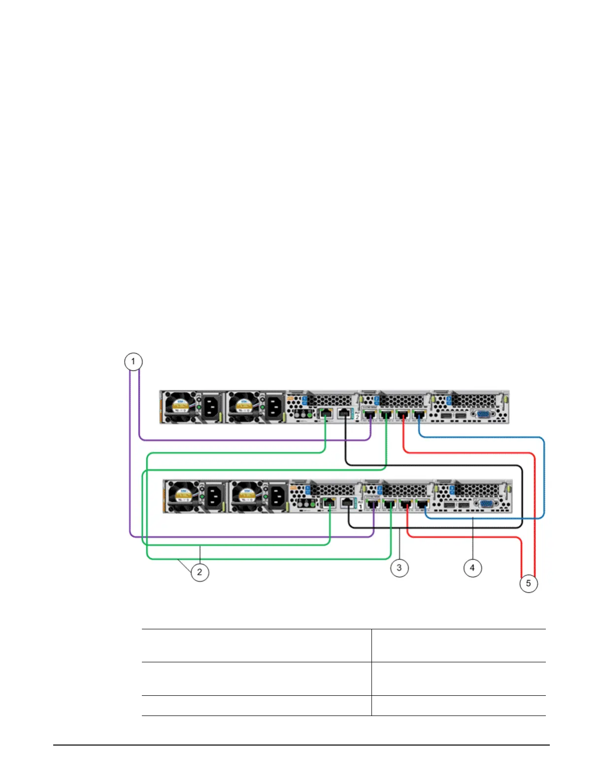
The following gure illustrates the cabling of the Pilot management interface.
Note: The colors of the cables that are shown in the gure are for illustration
purposes and do not reect the actual colors of the cables that are used to cable
the Oracle FS System.
Figure 79: Pilot wiring diagram (management connectivity)
Legend
1 NET 3 port to customer management
network
4 NET 0 port to NET 0 port
2 NET MGT port to NET 2 port 5 NET 1 port to Controller NET 3
port
3 SER MGT port to SER MGT port
124

 Loading...