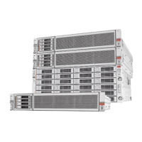
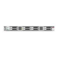
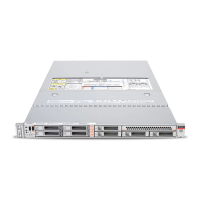
•
Mini-SAS to mini-SAS HD cables used to connect the Controller nodes and
the Drive Enclosure strings. The number of cables included in the
shipment depends upon the conguration of the system.
•
Mini-SAS to mini-SAS cables used to connect the Drive Enclosures within a
string. The number of cables included in the shipment depends upon the
conguration of the system.
Caution: Do not connect the power distribution units (PDUs) to external power
sources until the internal cabling is complete.
Procedure Overview
1 Congure the Cable Covers on the CMAs
2 Connect the Cables to Pilot 1
3 Connect the Cables to Pilot 2
4 Connect the Cables to Controller 1
5 Connect the Cables to Controller 2
6 Connect the SAS Cables to the Controllers
7 Connect the Controllers to the Drive Enclosures
8 Connect the SAS Cables to the Drive Enclosures
Configure the Cable Covers on the CMAs
To accommodate the volume of cables routed through the cable management
arms (CMAs) of the Controllers, you might have to replace the standard cable
covers on the CMAs with the large cable covers.
The large cable covers are included in the packaging. As a guideline, replace the
standard cable covers with the large cable covers for Oracle FS Systems with
eight SAS cables connected to the SAS HBAs on each Controller. For larger
systems congured with three SAS HBAs per Controller, you can remove the
cable covers completely from the CMAs to allow for the volume of SAS cables.
1 Open the cable cover currently aached to the Controller CMA.
2 Pull the cover o of the CMA.
Start at one end of the cable cover and work towards the other end of the
cable cover as you pry o the cable cover.
3 Snap the pins of the large cover into place on the CMA.
For systems with three SAS HBAs per Controller, leave the cable cover o
of the CMA.
4 Repeat these steps for the partner Controller.
Connect the Internal Cables
140
 Loading...
