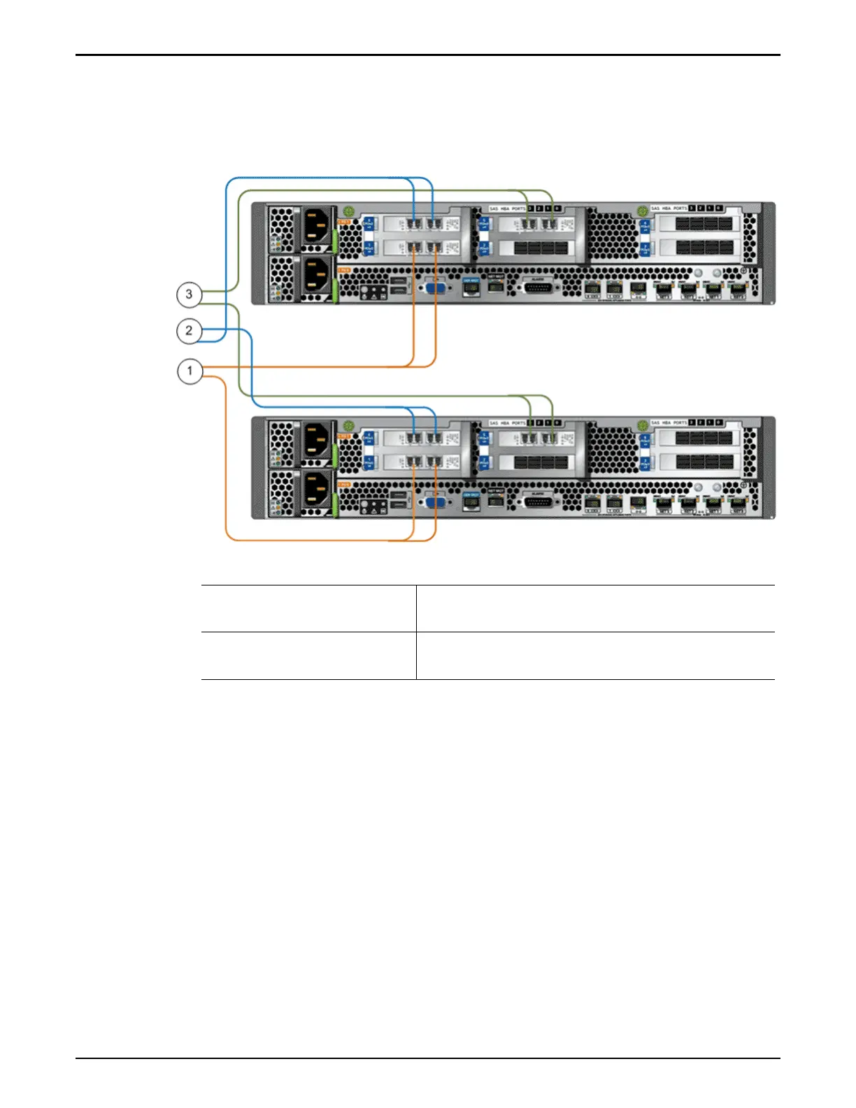
Note: The colors of the cables that are shown in the gure are for illustration
purposes and do not reect the actual colors of the cables that are used to cable
the Oracle FS System.
Figure 81: Controller wiring diagram (customer data network)
Legend
1 PCIe3 slot 1, HBA for SAN
connectivity (FC or iSCSI)
3 PCIe3 slot 5, HBA for SAN connectivity (FC or
iSCSI)
2 PCIe3 slot 4, HBA for SAN
connectivity (FC or iSCSI)
SAS Wiring Diagrams (Controller to Controller)
Complete back-end data path redundancy is accomplished by providing
Controller 1 and Controller 2 access to the data path channels for I/O module 0
and I/O module 1 at all times during normal operations:
•
The SAS connections between the Controller HBAs provide access to the
data path channels through HBA port 2 and port 3.
•
Controller 1 accesses the data path channels for I/O module 0 through
direct SAS connections to the Drive Enclosure strings through HBA port 1
and port 2.
•
Controller 1 accesses the data path channels for I/O module 1 through
Controller 2, HBA port 2 and port 3.
Wiring Diagrams
126

 Loading...