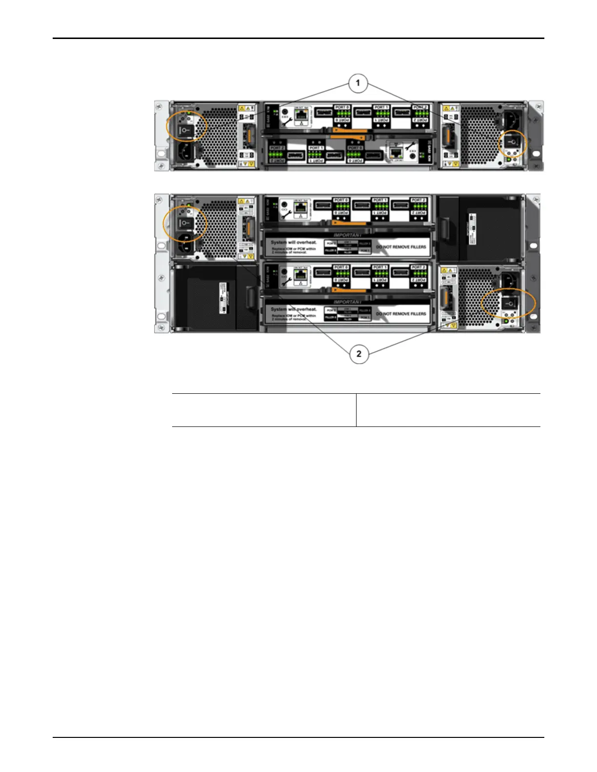
Figure 93: Power switches on the Drive Enclosures
Legend
1 The power switches on the
DE2-24P Drive Enclosure
2 The power switches on the
DE2-24C Drive Enclosure
4 Congure the seings for the Ethernet interface on a laptop.
Valid seings:
Address
10.0.0.10
Gateway
10.0.0.1
Netmask
255.255.255.0
Note: You use the laptop to congure the management IP addresses for the
Pilots.
5 Connect the laptop to the NET 3 port on Pilot 1.
Connecting a laptop to the NET 3 port on Pilot 1 ensures that Pilot 1
becomes the active Pilot when the system powers up.
Note: Both of the Pilots are clearly labeled as Pilot 1 and Pilot 2. In a
standard conguration, Pilot 1 is the boom Pilot in the rack. Pilot 2 is the
top Pilot in the rack.
System Power
155

 Loading...