TERMINAL LAYOUT
Specification Desc./Quantity
1 Injection telltale light
2 -
3 -
4 Lambda probe negative
5 Live supply
6 Battery-powered
7 Immobilizer aerial
8 Electric fan solenoid
9 Water temperature sensor
10 -
11 Lambda probe positive
12 engine stop switch
13 Engine speed sensor (+)
14 Fuel injector
15 Engine speed sensor (-)
16 Diagnostics socket output
17 Immobilizer LED
18 Side stand
19 -
20 Injection load solenoid
21 -
22 HV coil
23 -
24 Start up enabling
25 -
26 Ground lead Connected with: water temperature sensor, stand witch
and engine stop switch.
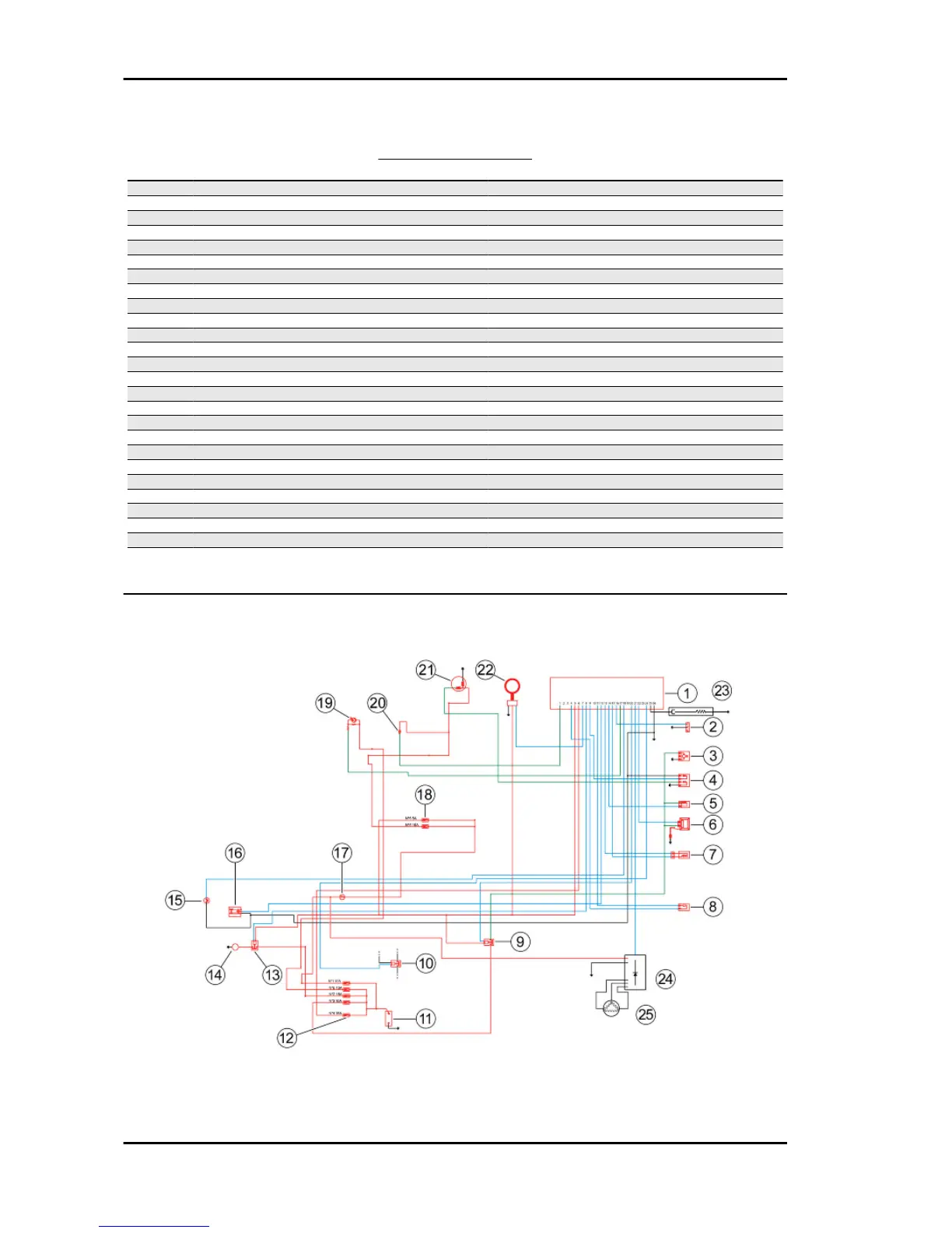
EMS circuit diagram
Injection Beverly 300 i.e.
INJEC - 172