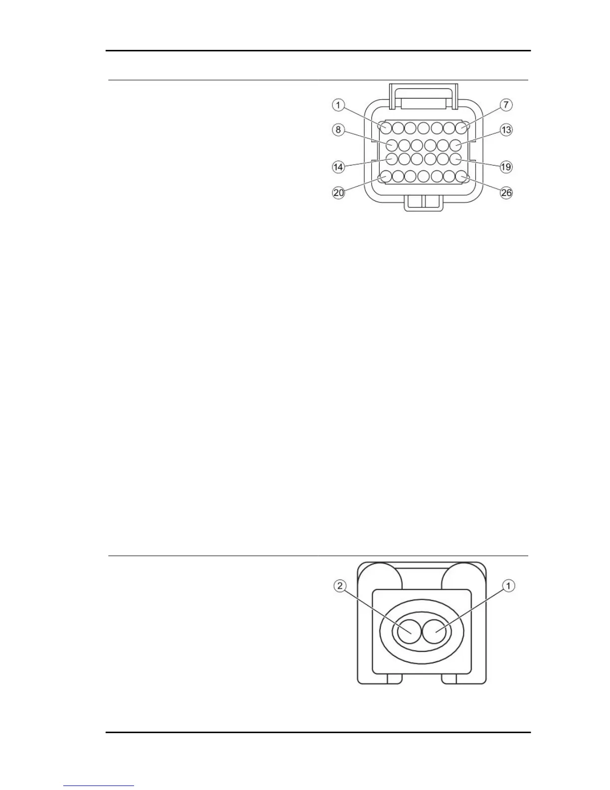
INJECTION ELECTRONIC CONTROL UNIT
CONNECTOR
1. Injection warning light (Brown-Black)
2. Not connected
3. Not connected
4. Lambda probe negative (White-Green)
5. Live power supply (Red-White)
6. Battery-powered (Orange-Black)
7. Immobilizer aerial (Orange-White)
8. Electric fan solenoid (Blue-Yellow)
9. Coolant temperature sensor (Sky blue-Green)
10. Not connected
11. Lambda probe positive (Sky blue-Black)
12. Engine stop switch (Green-Black)
13. Engine speed sensor positive (Red)
14. Injector negative (Yellow-Red)
15. Engine speed sensor negative (Brown)
16. Diagnostics socket (Purple-White)
17. Immobilizer LED (Red-Green)
18. Side stand (Sky blue)
19. Not connected
20. Injection load solenoid (Black-Purple)
21. Not connected
22. HV coil negative (Pink-Black)
23. Not connected
24. Start-up solenoid (Orange-Blue)
25. Fall sensor
26. Ground lead (Black)
INJECTOR CONNECTOR
1. Power from relay (Black-Green)
2. Negative from control unit (Yellow-Red)
Beverly 300 i.e. Electrical system
ELE SYS - 99