6) Check that the Blue-Black cable between the turn indicator control device and the turn indicator switch
is not interrupted.
7) Check that the Pink and White-Blue cables connecting the bulbs and the turn indicator switches are
not interrupted.
8) Check the bulbs ground connection.
level indicators
WARNING
ALL CONTINUITY TESTS MUST BE CARRIED OUT WITH THE CORRESPONDING CONNECTORS
DISCONNECTED.
If faults are detected:
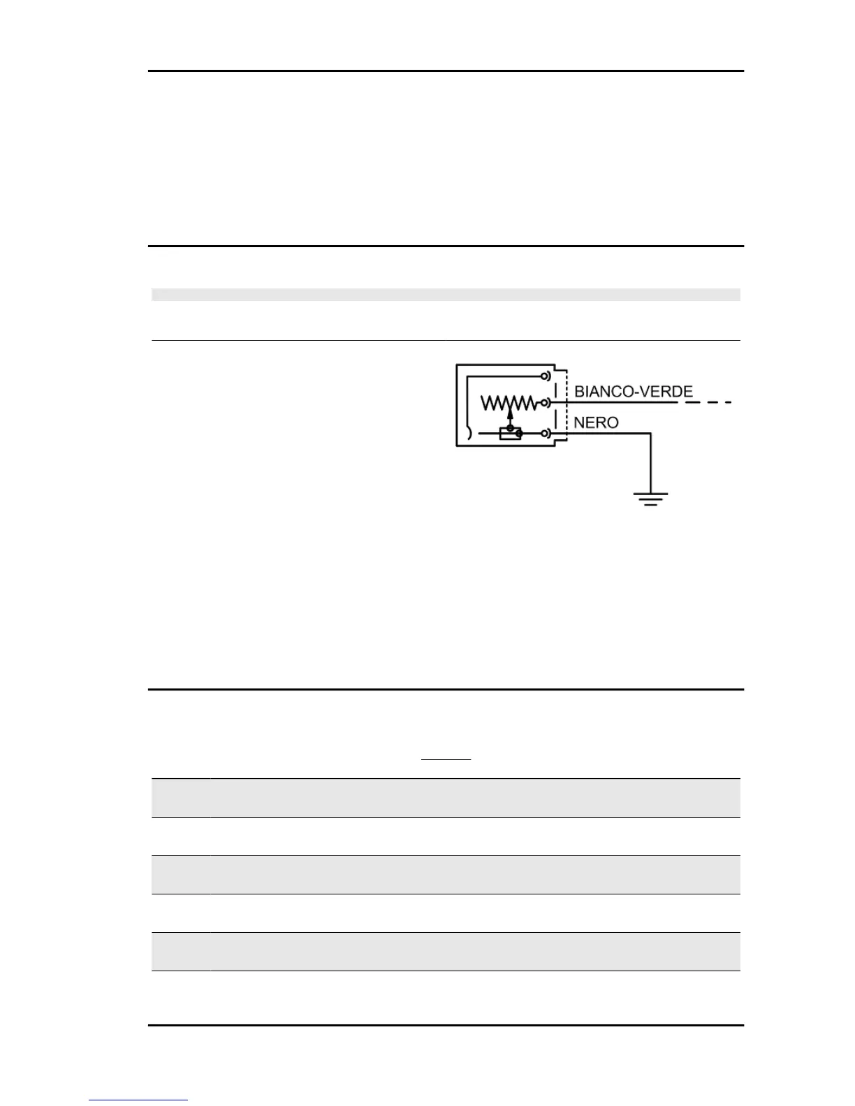
1) With a multimeter, check resistance values be-
tween the White-Green cable and the Black cable
of the fuel level transmitter by moving the arm with
the float.
2) If the transmitter operates correctly but the in-
dication on the instrument panel is not exact,
check that the cable harnesses between them are
not interrupted.
Electric characteristic
Resistance value when the tank is full
<= 7 Ω
Resistance value when the tank is empty
90 +13/-3 Ω
Lights list
BULBS
Specification
Desc./Quantity
1 Low beam light bulb Type: Halogen H7
Quantity: 1
Power: 12V - 55W
2 High beam light bulb Type: Halogen H7
Quantity: 1
Power: 12V - 55W
3 Front tail light bulb Type: LED
Quantity: 1 Right - 1 Left
Power: -
4 Front turn indicator light bulb Type: Spherical BAU 15s
Quantity: 1 Right - 1 Left
Power: 12V - 10W
5 Stop light/rear daylight running light bulb Type: LED
Quantity: 1 Right - 1 Left
Power: -
6 Rear turn indicator light bulb Type: Spherical BAU 15s
Quantity: 1 Right - 1 Left
Power: 12V - 10W
Beverly 300 i.e. Electrical system
ELE SYS - 89