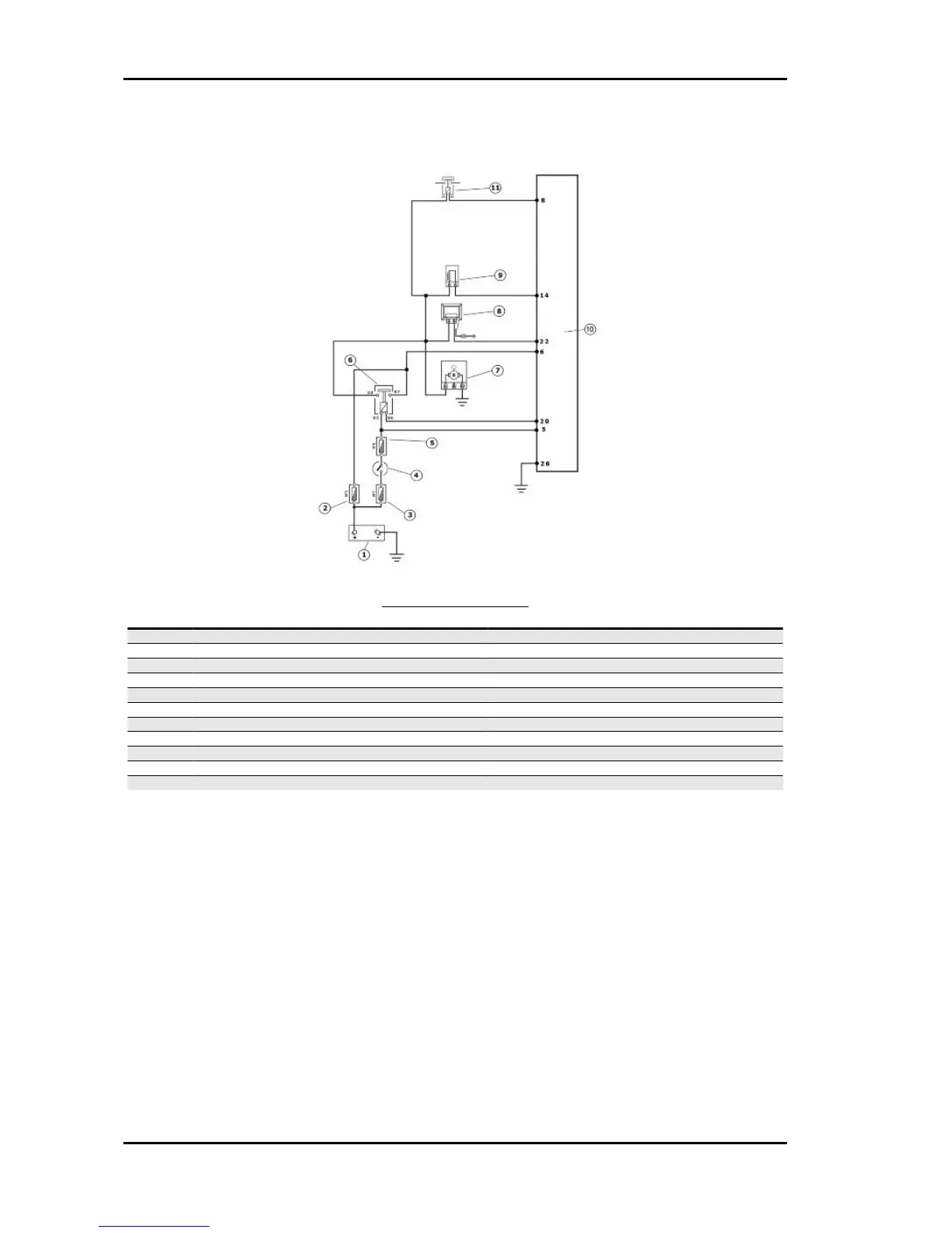
Pump supply circuit
INJECTION LOADS
Specification
Desc./Quantity
1 Battery 12V - 12 Ah
2 Fuse No. 3 10 A
3 Fuse No. 1 30 A
4 Ignition switch contacts
5 Fuse No. 6 5A
6 Injection load solenoid
7 Fuel pump
8 HV coil
9 Fuel injector
10 Injection ECU
11 Electric fan solenoid
When switched to «ON», the fuel pump starts to rotate for 2 seconds and then stops. When the engine
starts, in the presence of rpm timing signal the pump is continuously supplied.
ELECTRICAL DATA
•
Pump winding resistance ~ 1.5 Ohm
•
Input current during normal functioning 1.4 to 1.8 A
•
Input current to the closed hydraulic circuit ~ 2 A (to be checked with specific tool for fuel
pressure control, choking the circuit on the return pipe)
Injection Beverly 300 i.e.
INJEC - 180