Level indicators and enable signals section
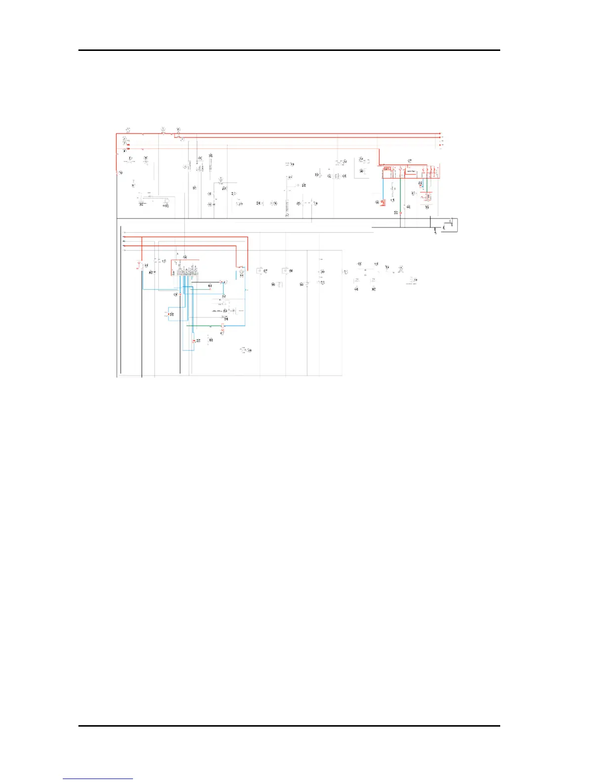
BASIC CIRCUIT DIAGRAM LEGEND:
1. F01-30A
2.F02-15A
3. F03-10A
4.F04-15A
5.Starter switch
6.F05-10A
7.F06-5A
10.12V - 10Ah Battery
36.Electronic control unit
37.Instrument panel
38.Fuel gauge
39.Engine temperature sensor
44.Immobilizer aerial
58.Injection load solenoid
60.Engine stop switch
61.Stand button (raised position)
65.Fuel injector
Electrical system Beverly 300 i.e.
ELE SYS - 72