R&S
®
ZVA / R&S
®
ZVB / R&S
®
ZVT GUI Reference
Trace Menu
Operating Manual 1145.1084.12 – 30 168
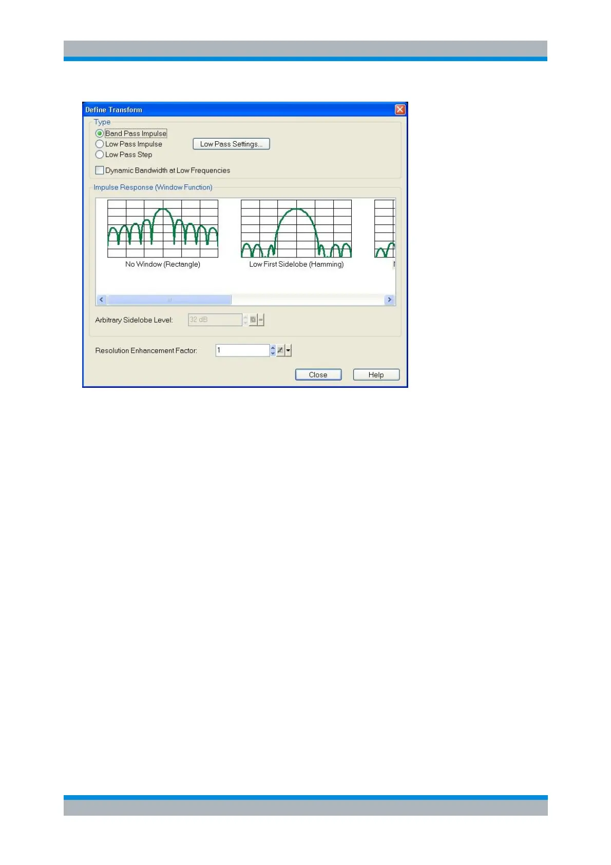
The radio buttons in the Type panel select a bandpass or lowpass transform. To calculate a
lowpass transform the sweep points must be on a harmonic grid (otherwise the analyzer will only
be able to calculate an approximate result and generate a warning). Low Pass Settings... opens a
dialog to establish or change a harmonic grid (not available for memory traces).
If Dynamic Bandwidth at Low Frequencies is enabled, the analyzer reduces the IF bandwidths at
receiver frequencies below 500 MHz by a frequency-dependent (dynamic) factor. This setting
complements the automatic bandwidth reduction for frequency sweeps with small start
frequencies; see Bandwidth reduction at low frequencies.
The bandwidth reduction reduces the trace noise at small frequencies and improves the accuracy
of the time domain transform. It is recommended to select Dynamic Bandwidth at Low
Frequencies when performing a low pass transformation.
The Impulse Response (Window Function) panel allows to select a window function (in the
frequency domain) to be applied to the active trace prior to the time domain transformation. The
analyzer always uses No Window (Rectangle) to calculate the time-gated frequency domain trace,
see background information in section Frequency Domain.
If an Arbitrary Sidelobes (Dolph-Chebychev) window is selected, the Arbitrary Sidelobe Level
(sidelobe suppression) can be set below the Impulse Response diagrams. The entered value is
the ratio of the power of the central lobe to the power of the first side lobe in dB.
The Resolution Enhancement Factor broadens the frequency range that the analyzer considers
for the time domain transform by a linear factor. A factor of 1 means that the original sweep range
and the measured sweep points are used; no additional assumptions are made. With higher
resolution enhancement factors, the measurement data is extrapolated using a linear prediction
method. As a result, the resolution in time domain can be improved.
The ideal resolution enhancement factor depends on the properties of the DUT. In distance to
fault measurements on cables, factors between 3 and 5 turned out to be a good choice.
For a comparison of the different transformation types and windows and for application examples please
also refer to the application note 1EZ44 which is posted on the R&S internet.