R&S
®
ZVA / R&S
®
ZVB / R&S
®
ZVT GUI Reference
Trace Menu
Operating Manual 1145.1084.12 – 30 171
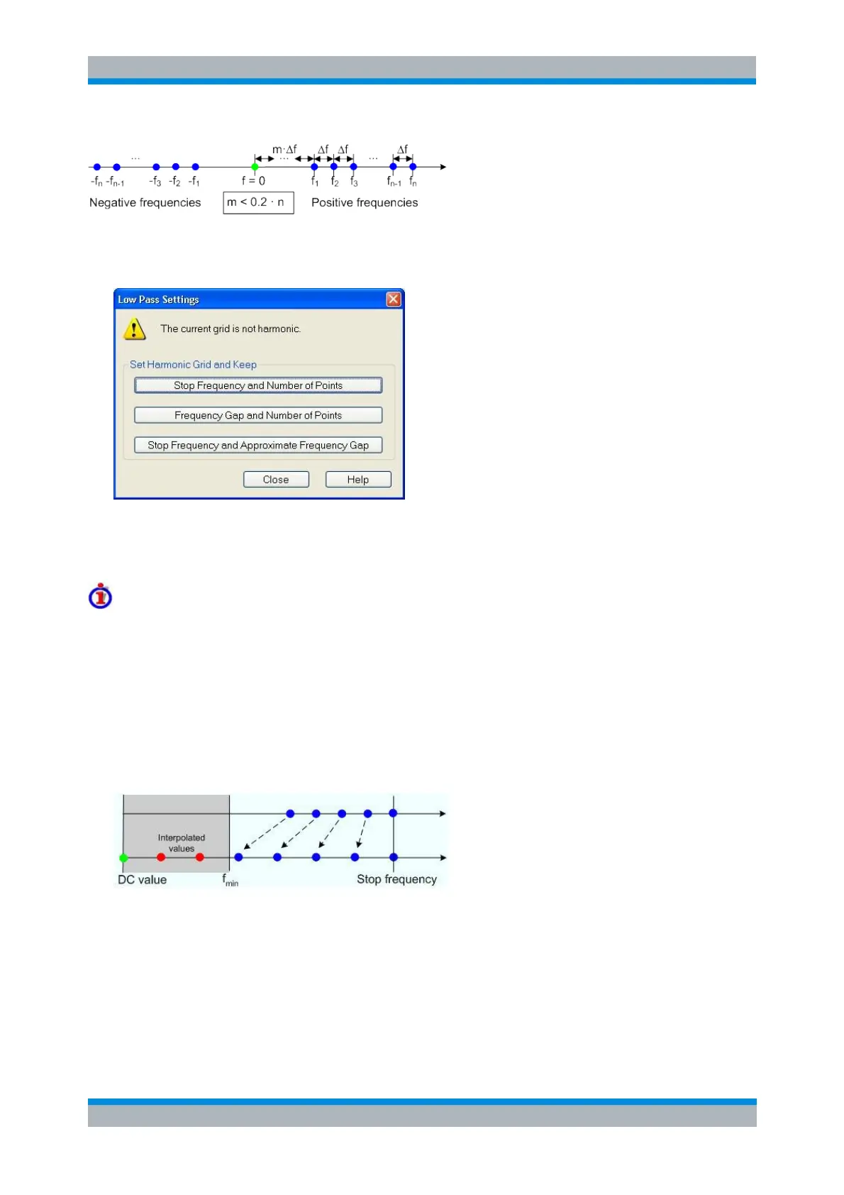
If a harmonic grid, including the DC value (f = 0) is mirrored to the negative frequency range, the result is
again an equidistant grid. The point symmetry with respect to the DC value makes harmonic grids suitable
for lowpass time domain transformations.
The three buttons in the Set Harmonic Grid... panel provide alternative algorithms for calculation of a
harmonic grid, based on the current sweep points.
Defining the low frequency sweep points
After calculating a harmonic grid, the analyzer must determine the value of the measured quantity at zero
frequency and possibly at additional points in the range between f = 0 and f = f
min
, where f
min
denotes the
minimum frequency of the analyzer.
The following figure shows a scenario where the harmonic grid was calculated with fixed Stop Frequency
and Number of Points. The DC value and the values at the two additional red points must be extrapolated
or interpolated according to the measured sweep points (blue dots) and the properties of the DUT. The
extrapolation of the DC value is described in section DC Value. The additional points between the DC
value and the first measured point are obtained by linear interpolation of the magnitude and phase by the
analyzer.
CALCulate<Chn>:TRANsform:TIME:LPASs KFSTop | KDFRequency |
KSDFrequency
CALCulate<Chn>:TRANsform:TIME:LPFRequency