R&S
®
ZVA / R&S
®
ZVB / R&S
®
ZVT GUI Reference
Channel Menu
Operating Manual 1145.1084.12 – 30 305
is made up of frequency converter ports, power control must be active for both of them (i.e. the power
control method must not be set to None or Mechanical Attenuator).
If True Differential Mode is activated, Tolerance defines the maximum deviation from the nominal
Amplitude and Phase relation of the generated differential signals.
Amplitude and phase tolerance for true differential mode and defined coherence mode
In True Differential Mode and Defined Coherence Mode one of the two involved ports serves as a
reference port, while amplitude and phase of the other port is adjusted until the desired amplitude and
phase difference is reached (e.g. 0 dB and 180° for True Differential Mode).
The tolerances define the maximum allowed deviation between nominal and actual amplitude and phase
differences. By default the adjustment stops if the desired amplitude and phase differences are met with a
tolerance of 0.1 dB and 1°, respectively.
Note that the tolerance settings apply to both the True Differential Mode and the Defined Coherence
Mode.
The tab also provides the following additional settings for the true differential mode with a frequency
converter. The frequency converter mode must be active to change these settings.
Receiver Frequency for True Diff Source Adjustment defines the receiver frequency which the
analyzer uses to adjust the desired amplitude and phase of the true differential signal. The
adjustment requires a measurement of the a- and b-waves at the physical ports which belong to
the balanced converter port.
By default the receiver frequency for the source adjustment is equal to the receiver frequency for
measurement, to be defined in the Receiver section of the Port Configuration dialog.
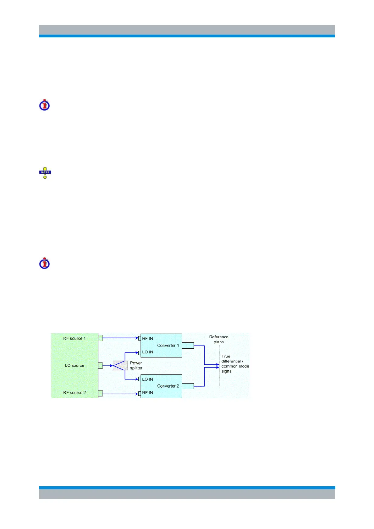
True differential mode with frequency converters
If the frequency converter mode is combined with true differential mode, the analyzer generates a true
differential or common mode stimulus signal at a calibrated reference plane which is located after two
frequency converter ports. To achieve this, two frequency converters with independent sources are
combined to form a balanced converter port. The frequency converters must provide the RF drive signal
simultaneously so that a third, independent LO signal is required. This means that the standard test setup
described in section Converter Control – Connecting the Frequency Converters must be replaced by the
following scheme:
Depending on the network analyzer type and the number of independent sources available, different test
setups are possible.
1. R&S ZVA24/40/50 with 4 ports and 2 generators
Ports 1 and 2 are driven by the same source (coupled ports); ports 3 and 4 by a different source. Possible
connection: Analyzer port 1 to RF IN (converter 1), analyzer port 3 to RF IN (converter 2), the LO signal
for both converters is provided by an external generator in combination with an external power splitter.