R&S
®
ZVA / R&S
®
ZVB / R&S
®
ZVT GUI Reference
Channel Menu
Operating Manual 1145.1084.12 – 30 327
The RF signal is the stimulus signal that the analyzer generates with the current channel settings.
After a reset the frequency and power of the RF signal is as defined in the Channel – Stimulus
menu. The RF signal parameters can be changed in the Set Power... and Set Frequencies...
dialogs.
The Local Oscillator (LO) signals are two additional RF signals that are either generated by the
network analyzer (at the ports that are not used for the RF and IF signals, i.e. port 3, 4...) or by
external generators. Both LO signals are at the same frequency. The first LO signal is fed to the
LO input of the MUT, the second to the additional mixers using an appropriate power splitter (not
in the diagram). If necessary, appropriate amplifiers can be used in addition. With a second power
splitter or a 3-way splitter, it is also possible to supply all three mixers from a single source.
On four-port analyzers, it is recommended to use the (coupled) analyzer ports port 3 and port 4 for
the LO signals.
The IF signal is the mixer output signal (mixing product), which is at one of the following
frequencies: IF = |LO – RF|, i.e. LO – RF (for LO > RF) or IF = RF – LO (for RF > LO) or IF = LO +
RF. The IF frequency band is selected in the Set Frequencies... dialog.
The lowpass or highpass filter rejects the undesired mixing product that might impair the accuracy
of the measurement and of the mixer vector calibration. The required filter type and cut-off
frequency are displayed in the diagram, depending on the RF / LO frequencies and the selected
IF band.
If the mixer under test is measured in down-converting mode (IF = RF – LO or IF = LO – RF), a
lowpass filter must be used to reject the up-converted IF signal at IF = RF + LO. If fed to the IF
input of the MEAS mixer, the RF + LO signal would be down-converted to RF, which would make
it indistinguishable from the RF – LO signal, up-converted to RF. The cut-off frequency of the
lowpass filter must be between Max(RF – LO) and Min(RF + LO).
If the mixer under test is measured in up-converting mode (IF = RF + LO), a highpass filter must
be used to reject the down-converted IF signal at IF = RF – LO. If fed to the IF input of the MEAS
mixer, the RF – LO signal would be up-converted to RF, which would make it indistinguishable
from the RF + LO signal, down-converted to RF. The cut-off frequency of the highpass filter must
be between Max(RF – LO) and Min(RF + LO).
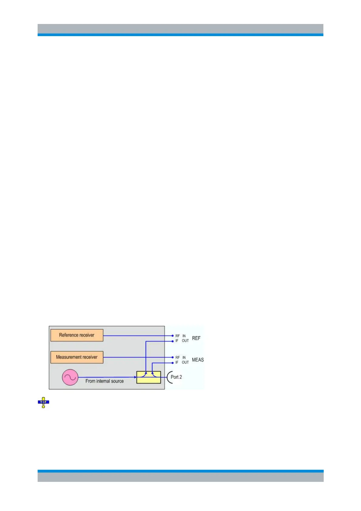
The additional mixer MEAS converts the filtered IF signal from the mixer under test back to the RF
frequency which is fed to the measurement receiver at port 2.
The additional mixer REF converts the IF signal from the internal source at port 2 to an RF signal
which is fed to the reference receiver.
The signal description above with the swept RF signal and the LO signal at a fixed frequency
corresponds to the default configuration. In the Set Frequencies dialog, you can select any of the signals
as a Sweep/CW signal. You can set the frequency range of this signal via Start/Stop or CW Frequency. A
second signal is at a Fixed frequency, and the third at the calculated sum or difference frequency (Auto).
The vector mixer measurement is also compatible with different sweep types, e.g. a power sweep. The
labeling of the input and output signals of the MUT depends on the sweep type.