R&S
®
ZVA / R&S
®
ZVB / R&S
®
ZVT GUI Reference
Channel Menu
Operating Manual 1145.1084.12 – 30 377
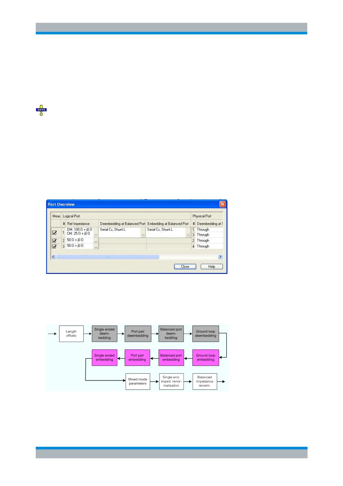
Deembedding at Balanced Port and Embedding at Balanced Port show the 4-port transformation
networks to be numerically added or removed at balanced (logical) ports. Off denotes that no
(de)embedding operation is performed.
Deembedding at Single Ended Port and Embedding at Single Port show the 2-port transformation
networks to be numerically added or removed at single ended (physical) or balanced (logical)
ports. Off denotes that no (de)embedding operation is performed.
A ground loop cannot be assigned to a logical or physical analyzer port, so ground loop (de-
)embedding is not shown in the Port Overview dialog. The same applies to port pair (de-)embedding which
involves pairs of physical ports.
Combination of Different (De-)Embedding Networks
In the Port Overview dialog, it is possible to select a combination of 4-port and 2-port networks to be
numerically added/removed at balanced (logical) ports, and to select 2-port networks at single ended
(physical) ports. The following example shows the full configuration for a four-port analyzer where the
physical ports 1 and 3 form a balanced port with the logical port no. 1 and the remaining ports 2 and 4 are
single ended.
The port overview configuration above corresponds to the measurement circuits shown in steps 1 to 5
below.
The different steps for deembedding and embedding are carried out in the following order (the figure also
contains possible ground loop and port pair (de-)embedding stages which are not shown in the Port
Overview dialog):
This means that the real networks are removed before virtual networks are added. For a single balanced
port with all single ended and balanced port (de-)embedding networks enabled, the 4 (de-)embedding
steps are carried out in the following order:
1. Initial situation: DUT embedded in 2-port and 4-port networks (only 1 port shown)