R&S
®
ZVA / R&S
®
ZVB / R&S
®
ZVT GUI Reference
Channel Menu
Operating Manual 1145.1084.12 – 30 432
1. Select Physical Port Connectors and calibration kits at all calibrated ports.
2. Compile Calibrations: Select a calibration type and the physical ports to be calibrated (skipped for
predefined calibrations).
3. Measure Standards: Acquire measurement data for all standards required for the selected
calibration type.
4. Reference Plane Transformation (NIST Multiline TRL only): For a NIST Multiline TRL calibration it
is possible to account for a reference plane shift (optional).
5. Apply: Calculate the resulting system error correction data (error terms) from the measurement
data of the standards and apply the result to the active channel.
A successful calibration will supersede the previous calibration, discarding all previous system error
correction data. To keep older correction data you can transfer them into a Cal Pool using the Calibration
Manager.
The system error correction data determined in a calibration procedure are stored on the analyzer. You
can read these correction data using the remote control command [SENSe<Ch>:]CORRection:CDATa.
You can also replace the correction data of the analyzer by your own correction data sets.
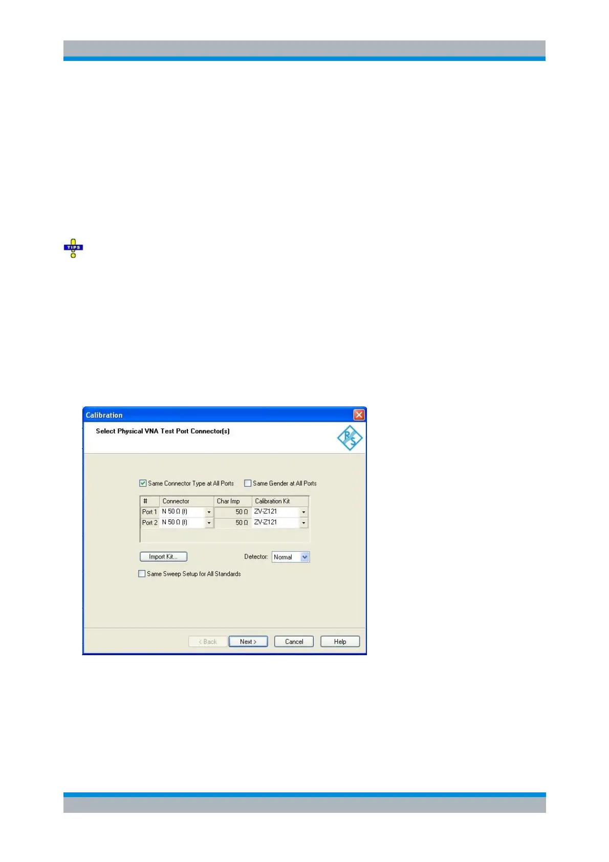
Select Connectors
The first dialog of the calibration wizard displays a table to select the connectors and calibration kits for all
calibrated physical ports, the detector, and the sweep setup.
The check boxes above the table allow you to select equal connector types and genders at all ports. For
some multi-port calibration types, the port connector types must be equal, e.g. because they require a
Through standard with known characteristics.
The table contains the following rows:
Physical Port Number #
The ports (and therefore the number of table rows) are determined by the active calibration type