R&S
®
ZVA / R&S
®
ZVB / R&S
®
ZVT GUI Reference
Channel Menu
Operating Manual 1145.1084.12 – 30 455
attenuation.
You can also save the displayed list to a power meter correction list file with extension (*.pmcl)
and re-load it in later sessions (Save List..., Load List...).
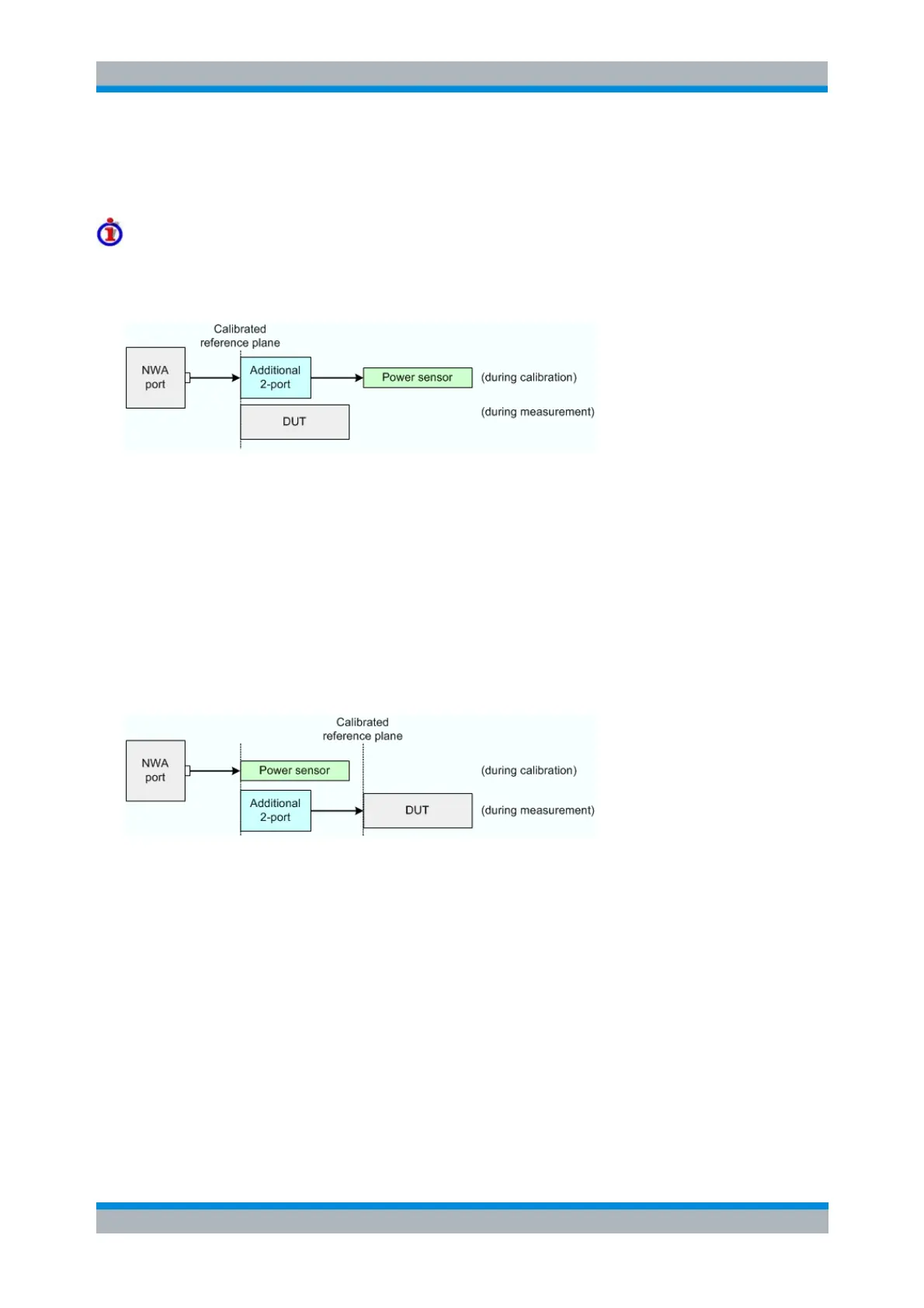
Test setups with "additional two-port" devices
The two test setups for additional two-ports can be depicted as follows.
Case A: 2-port in front of power sensor (during calibration)
Test and measurement procedure:
1. Perform the calibration with the additional two-port between the analyzer port and the power sensor.
During the calibration the analyzer increases the power sensor values by the 2-port transmission
coefficients. The calibrated reference plane corresponds to the input of the additional 2-port.
2. Perform the measurement without the additional two-port.
Practical example:
An adapter or attenuator with known attenuation is needed to connected the power sensor to the
NWA test port. The transmission coefficients of the adapter are used for the power meter
correction.
Case B: 2-port in front of DUT (during measurement)
Test and measurement procedure:
1. Perform the calibration without the additional two-port. During the calibration the analyzer decreases the
power sensor values by the 2-port transmission coefficients. The calibrated reference plane corresponds
to the output of an additional 2-port which is placed in-between the NWA port and the DUT.
2. Perform the measurement with the additional two-port.
Practical example:
On-wafer measurements. The power sensor cannot be directly connected to the input of the DUT.
The transmission coefficients of the wafer probe are used for the power meter correction.
[SENSe<Ch>:]PMMO ON | OFF
SOURce<Ch>:POWer:CORRection:TCOefficient[:STATe]
SOURce<Ch>:POWer:CORRection:TCOefficient:CALibration
SOURce<Ch>:POWer:CORRection:TCOefficient:INSert
SOURce<Ch>:POWer:CORRection:TCOefficient:DEFine