R&S
®
ZVA / R&S
®
ZVB / R&S
®
ZVT GUI Reference
Channel Menu
Operating Manual 1145.1084.12 – 30 472
The conversion formula for one-port standards has an additional factor 1/2 on the right-hand side.
The reason for this factor is that the Loss in dB accounts for the attenuation along the forward and
the reverse path (no matter how often the wave actually propagates through the line), whereas the
Offset Loss is proportional to the attenuation of the line.
To determine an offset loss value experimentally, measure the delay in seconds and the loss in dB
at 1 GHz and use the formula above.
The default Loss or Offset Loss is zero.
The impedance for waveguides is frequency-dependent. If a waveguide line type is selected in the
Offset Model dialog, the Char. Impedance field is disabled and indicates "varies" instead of a definite
impedance value. Moreover no Loss or Offset Loss can be set.
Offset parameters and standard types
Offset parameters are used to describe all types of standards except the Sliding Match and the
Attenuation.
The Sliding Match is a one-port standard with variable load parameters (sliding load) and
unspecified length. The reference impedance is fixed and equal to the characteristic impedance of
the connector type. No load and offset parameters need to be set.
The Attenuation is a two-port standard which is fully matched in both directions (the reflection
factor at both ports is zero). No load and offset parameters need to be set.
[SENSe<Ch>:]CORRection:CKIT:<conn_type>:<std_type>
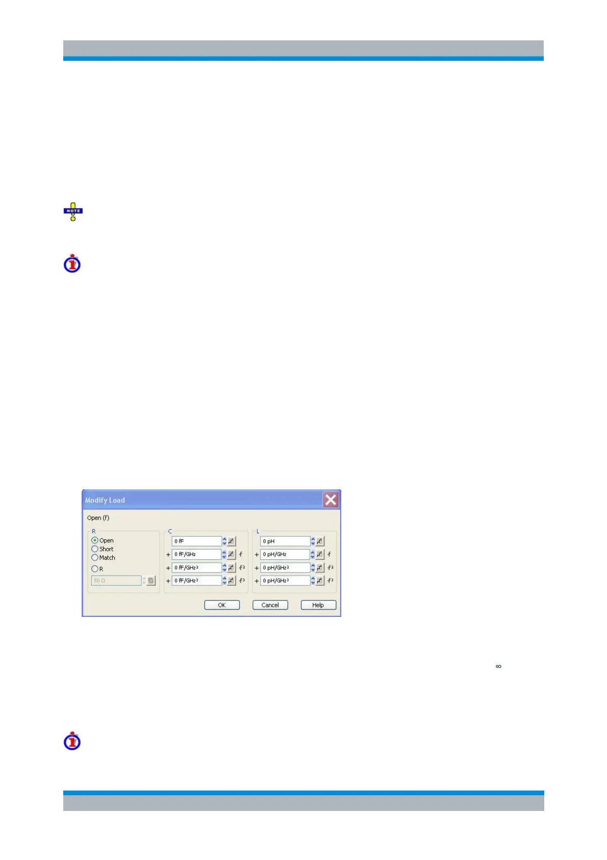
Modify Load
Specifies the load parameters for a particular calibration standard describing its terminal impedance. This
dialog is opened from the Add or View / Modify Standard... dialog (Modify Load... button).
The circuit model for the load consists of capacitance C which is connected in parallel to an inductance L
and a resistance R, both connected in series.
R is the constant resistive contribution. It is possible to select a special value (Open for Ω so
that the inductance coefficients are irrelevant, Short for 0 Ω, Match for the reference impedance of
the current connector type) or set any resistance R.
The fringing capacitance C and the residual inductance L are both assumed to be frequency-
dependent and approximated by the first four terms of the Taylor series around f = 0 Hz.
Load parameters and standard types