R&S
®
ZVA / R&S
®
ZVB / R&S
®
ZVT GUI Reference
System Menu
Operating Manual 1145.1084.12 – 30 545
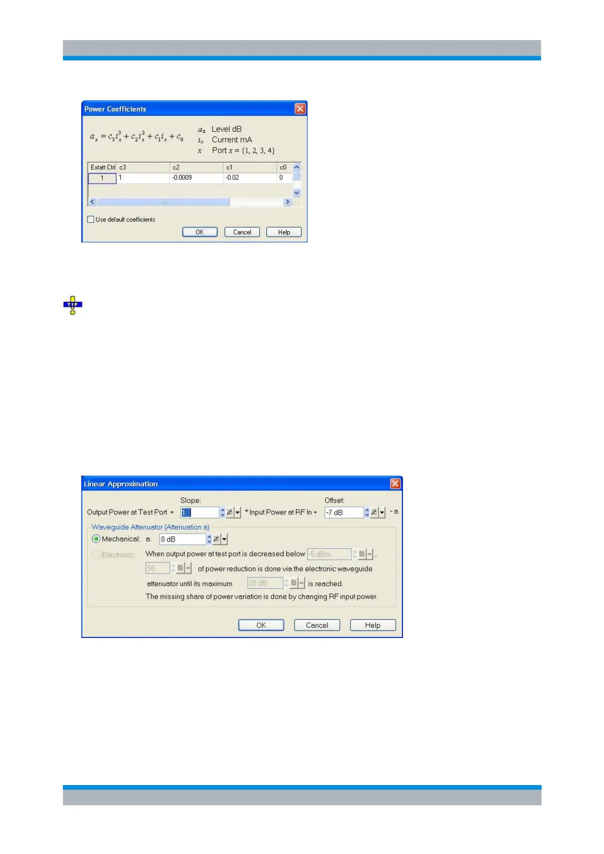
Keep Use default coefficients checked to use a set of default power coefficients, providing acceptable
output power control for arbitrary converters. For accurate measurements always use the actual power
coefficients of the currently connected converter.
A label with the four polynomial coefficients c
0
, c
1
, c
2
, and c
3
is affixed to each converter. Don't forget
to overwrite the coefficients whenever you connect a new converter to a NWA port.
[SENSe<Ch>:]FREQuency:CONVersion:DEVice:PCOefficient<Port>
[SENSe<Ch>:]FREQuency:CONVersion:DEVice:PCOefficient<Port>:DEFault
Linear Approximation
The Linear Approximation dialog configures a linear model for the converter output power at a specific
port. It can be opened from the Lin. Approx Coefficients button in the Port<i> Power Control dialog.
This power control mode can be used for converters with electronic attenuator and some converter types,
like R&S ZVA-Z90 and R&S ZVA-Z110 var. 03 that have nearly linear power transfer characteristics (P
out
vs P
RFin
on a dBm scale). The power transfer curve is approximated by a straight line described by slope
and offset. If the converter has an electronic attenuator, it is additionally used in order to control the output
power. The mechanism used to control the power depends on the output power level. At high power, the
electronic waveguide attenuator settings are fixed and output power is controlled by varying the input
power. In a medium power range, a selectable portion of the attenuation is contributed by the electronic
attenuator, until it reaches its maximum attenuation. Below this point, only RF input power is varied again.