RL78/G1H CHAPTER 8 TIMER RJ
R01UH0575EJ0120 Rev. 1.20 Page 224 of 920
Dec 22, 2016
8.2 Configuration of Timer RJ
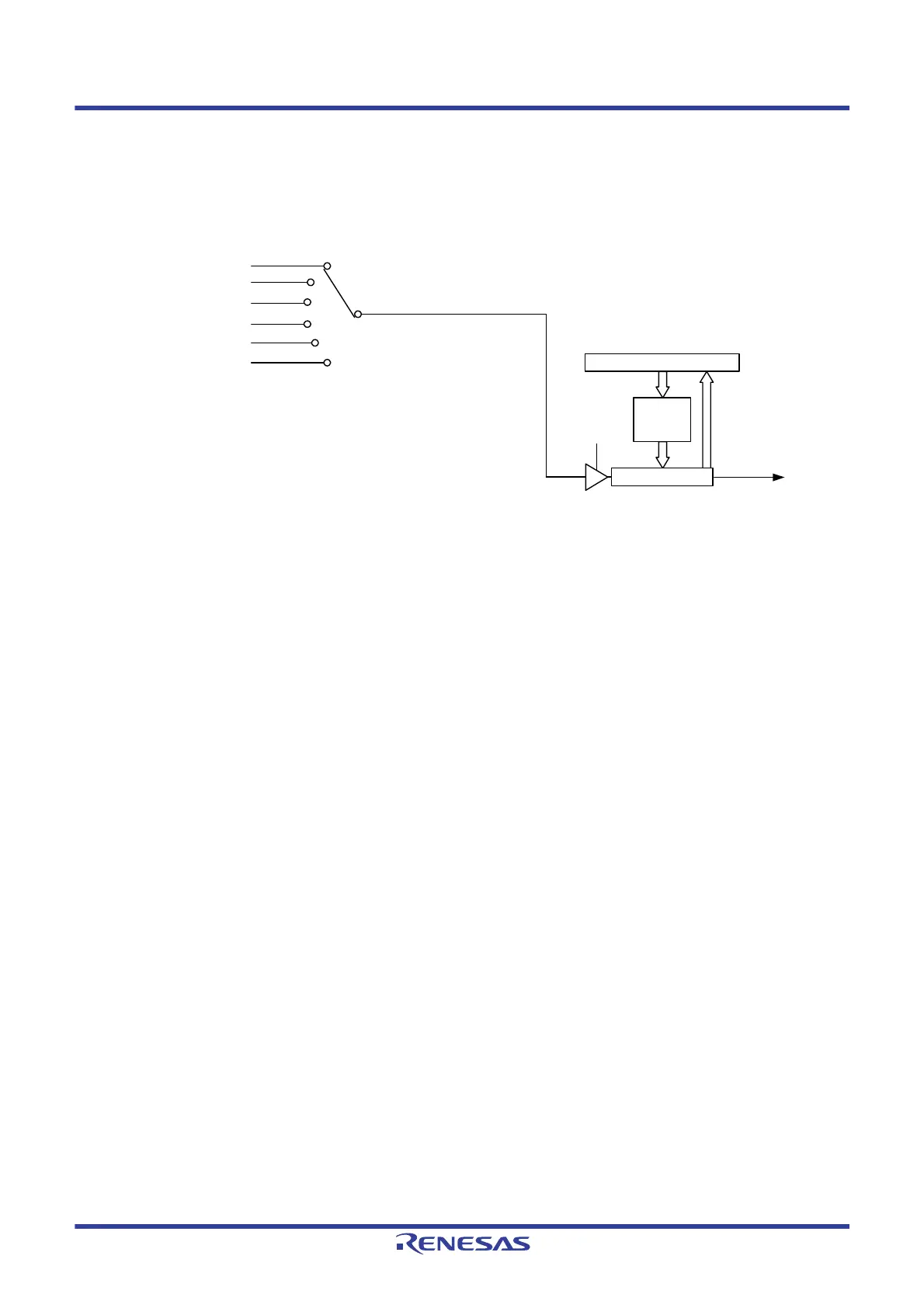
Figure 8 - 1 shows the Timer RJ Block Diagram.
Figure 8 - 1 Timer RJ Block Diagram
Note When selecting fIL as the count source, set the WUTMMCK0 bit in the subsystem clock supply mode control register
(OSMC) to 1. However, f
IL cannot be selected as the count source for timer RJ when fSUB is selected as the count
source for the real-time clock or the 12-bit interval timer.
Data bus
= 000B
= 001B
= 011B
TSTART, TSTOP: Bits in TRJCR0 register
TCK0 to TCK2: Bits in TRJMR0 register
f
CLK
fCLK/8
f
CLK/2
TCK2〜TCK0
TSTART
= 100B
= 101B
= 110B
fSUB
fIL
Note
Event input from ELC
TRJ0 counter
16-bit counter
16-bit
reload
register
Timer RJ0
interrupt
 Loading...


