RL78/G1H CHAPTER 7 TIMER ARRAY UNIT
R01UH0575EJ0120 Rev. 1.20 Page 168 of 920
Dec 22, 2016
7.3.12 Timer output mode register m (TOMm)
The TOMm register is used to control the timer output mode of each channel.
When a channel is used for the independent channel operation function, set the corresponding bit of the channel
to be used to 0.
When a channel is used for the simultaneous channel operation function (PWM output), set the corresponding bit
of the master channel to 0 and the corresponding bit of the slave channel to 1.
The setting of each channel n by this register is reflected at the timing when the timer output signal is set or reset
while the timer output is enabled (TOEmn = 1).
The TOMm register can be set by a 16-bit memory manipulation instruction.
The lower 8 bits of the TOMm register can be set with an 8-bit memory manipulation instruction with TOMmL.
Reset signal generation clears this register to 0000H.
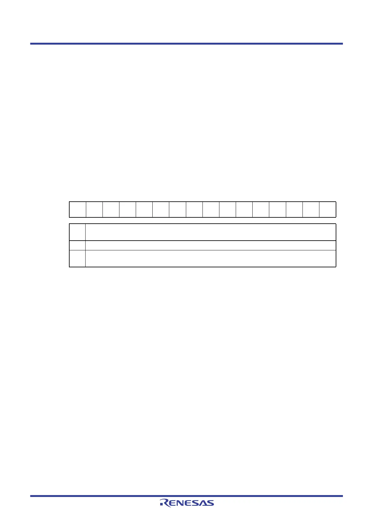
Figure 7 - 24 Format of Timer output mode register m (TOMm)
Caution Be sure to clear bits 15 to 4 , 2 to 0 to “0” in TOM0 register. Set to 0000H register in TOM1 register.
Remark
m: Unit number (m = 0, 1)
n: Channel number
n = 0 to 3 (n = 0, 2 for master channel)
p: Slave channel number
n = 0, p = 1, 2, 3
n = 2, p = 3
(For details of the relation between the master channel and slave channel, refer to
7.4.1 Basic rules of
simultaneous channel operation function
)
Address: F01BEH, F01BFH (TOM0), F01FEH, F01FFH (TOM1) After reset: 0000H R/W
Symbol1514131211109876543210
TOMm000000000000
TOMm
3
TOMm
2
TOMm
1
0
TOM
mn
Control of timer output mode of channel n
0 Master channel output mode (to produce toggle output by timer interrupt request signal (INTTMmn))
1 Slave channel output mode (output is set by the timer interrupt request signal (INTTMmn) of the master channel,
and reset by the timer interrupt request signal (INTTMmp) of the slave channel)
 Loading...


