RL78/G1H CHAPTER 13 A/D CONVERTER
R01UH0575EJ0120 Rev. 1.20 Page 286 of 920
Dec 22, 2016
13.3.1 Peripheral enable register 0 (PER0)
This register is used to enable or disable supplying the clock to the peripheral hardware. Clock supply to a
hardware macro that is not used is stopped in order to reduce the power consumption and noise.
When the A/D converter is used, be sure to set bit 5 (ADCEN) of this register to 1.
The PER0 register can be set by a 1-bit or 8-bit memory manipulation instruction.
Reset signal generation clears this register to 00H.
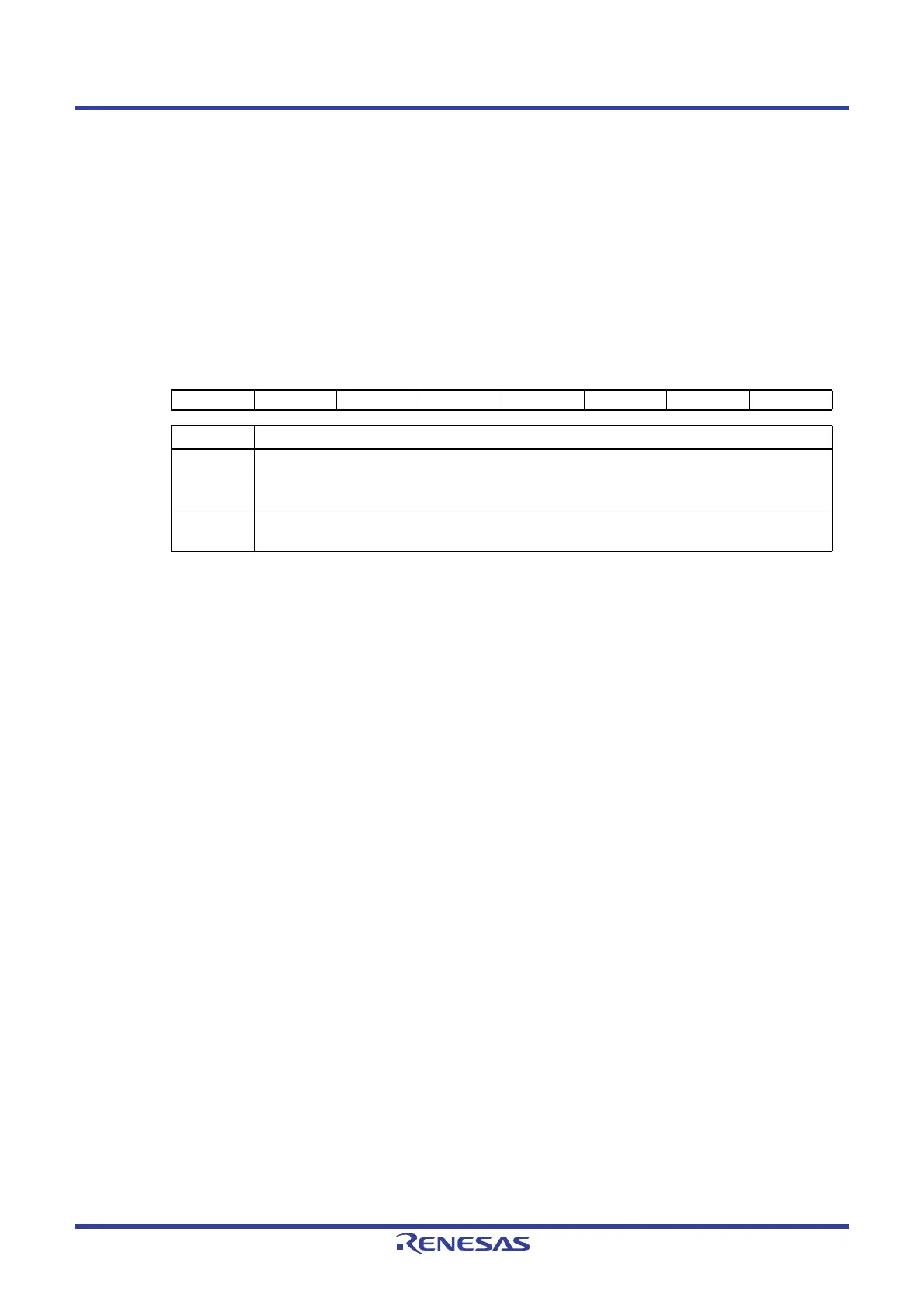
Figure 13 - 2 Format of Peripheral enable register 0 (PER0)
Caution When setting the A/D converter, be sure to set the following registers first while the ADCEN bit is set
to 1.
If ADCEN = 0, the values of the A/D converter control registers are cleared to their initial values and
writing to them is ignored (except for port mode registers 2, 12, and 15 (PM2, PM12, PM15), port mode
control register 12 (PMC12), and A/D port configuration register (ADPC)).
• A/D converter mode register 0 (ADM0)
• A/D converter mode register 1 (ADM1)
• A/D converter mode register 2 (ADM2)
• 10-bit A/D conversion result register (ADCR)
• 8-bit A/D conversion result register (ADCRH)
• Analog input channel specification register (ADS)
• Conversion result comparison upper limit setting register (ADUL)
• Conversion result comparison lower limit setting register (ADLL)
• A/D test register (ADTES)
Address: F00F0H After reset: 00H R/W
Symbol <7> <6> <5> <4> <3> <2> <1> <0>
PER0 RTCEN IICA1EN ADCEN IICA0EN SAU1EN SAU0EN TAU1EN TAU0EN
ADCEN Control of A/D converter input clock supply
0 Stops input clock supply.
• SFR used by the A/D converter cannot be written.
• The A/D converter is in the reset status.
1 Enables input clock supply.
• SFR used by the A/D converter can be read/written.
 Loading...


