RL78/G1H CHAPTER 16 DATA TRANSFER CONTROLLER (DTC)
R01UH0575EJ0120 Rev. 1.20 Page 519 of 920
Dec 22, 2016
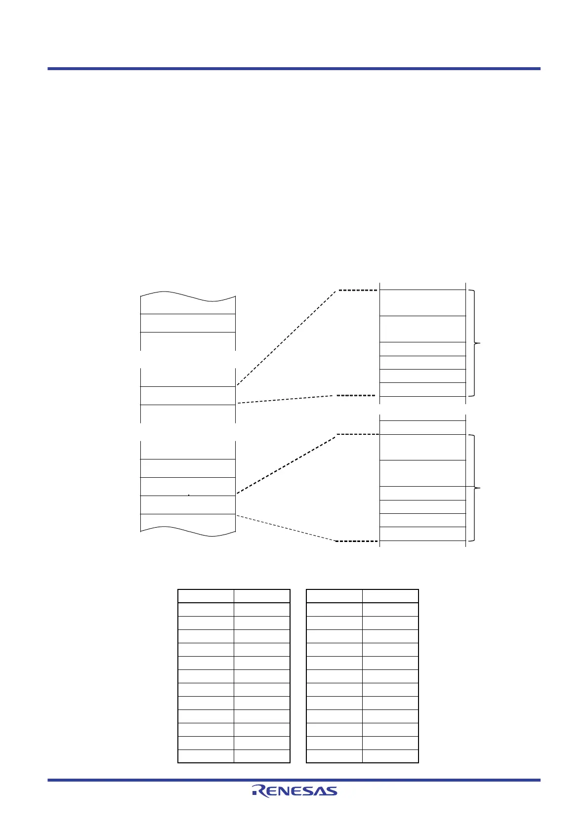
16.3.2 Control Data Allocation
Control data is allocated beginning with each start address in the order: Registers DTCCRj, DTBLSj, DTCCTj,
DTRLDj, DTSARj, and DTDARj (j = 0 to 23).
The higher 8 bits for start addresses 0 to 23 are set by the DTCBAR register, and the lower 8 bits are separately
set according to the vector table assigned to each activation source.
Figure 16 - 3 shows Control Data Allocation.
Note 1. Change the data in registers DTCCRj, DTBLSj, DTCCTj, DTRLDj, DTSARj, and DTDARj when the
corresponding bit among bits DTCENi0 to DTCENi7 (i = 0 to 4) in the DTCENi register is set to 0
(activation disabled).
Note 2. Do not access DTCCRj, DTBLSj, DTCCTj, DTRLDj, DTSARj, or DTDARj using a DTC transfer.
Figure 16 - 3 Control Data Allocation
Table 16 - 4 Start Address of Control Data
j Address j Address
11 Fxx98H 23 FxxF8H
10 Fxx90H 22 FxxF0H
9 Fxx88H 21 FxxE8H
8 Fxx80H 20 FxxE0H
7 Fxx78H 19 FxxD8H
6 Fxx70H 18 FxxD0H
5 Fxx68H 17 FxxC8H
4 Fxx60H 16 FxxC0H
3 Fxx58H 15 FxxB8H
2 Fxx50H 14 FxxB0H
1 Fxx48H 13 FxxA8H
0 Fxx40H 12 FxxA0H
Control data 23
Control data j
Control data 2
Control data 1
Control data 0
DTDAR15 register
DTSAR15 register
DTRLD15 register
DTCCT15 register
DTBLS15 register
DTCCR15 register
DTCCR1 register
DTDAR0 register
DTSAR0 register
DTRLD0 register
DTCCT0 register
DTBLS0 register
DTCCR0 register
Fxx40H
Fxx48H
Fxx50H
FxxyyH
FxxF8H
Start address of
control data
Fxx40H
Fxx41H
Fxx42H
Fxx43H
Fxx44H
Fxx46H
Fxx48H
Address
When j = 15
8 bytes
8 bytes
xx: Set value of DTCBAR register
FxxB8H
FxxB9H
FxxBAH
FxxBBH
FxxBCH
FxxBEH
 Loading...


