RL78/G1H CHAPTER 27 FLASH MEMORY
R01UH0575EJ0120 Rev. 1.20 Page 808 of 920
Dec 22, 2016
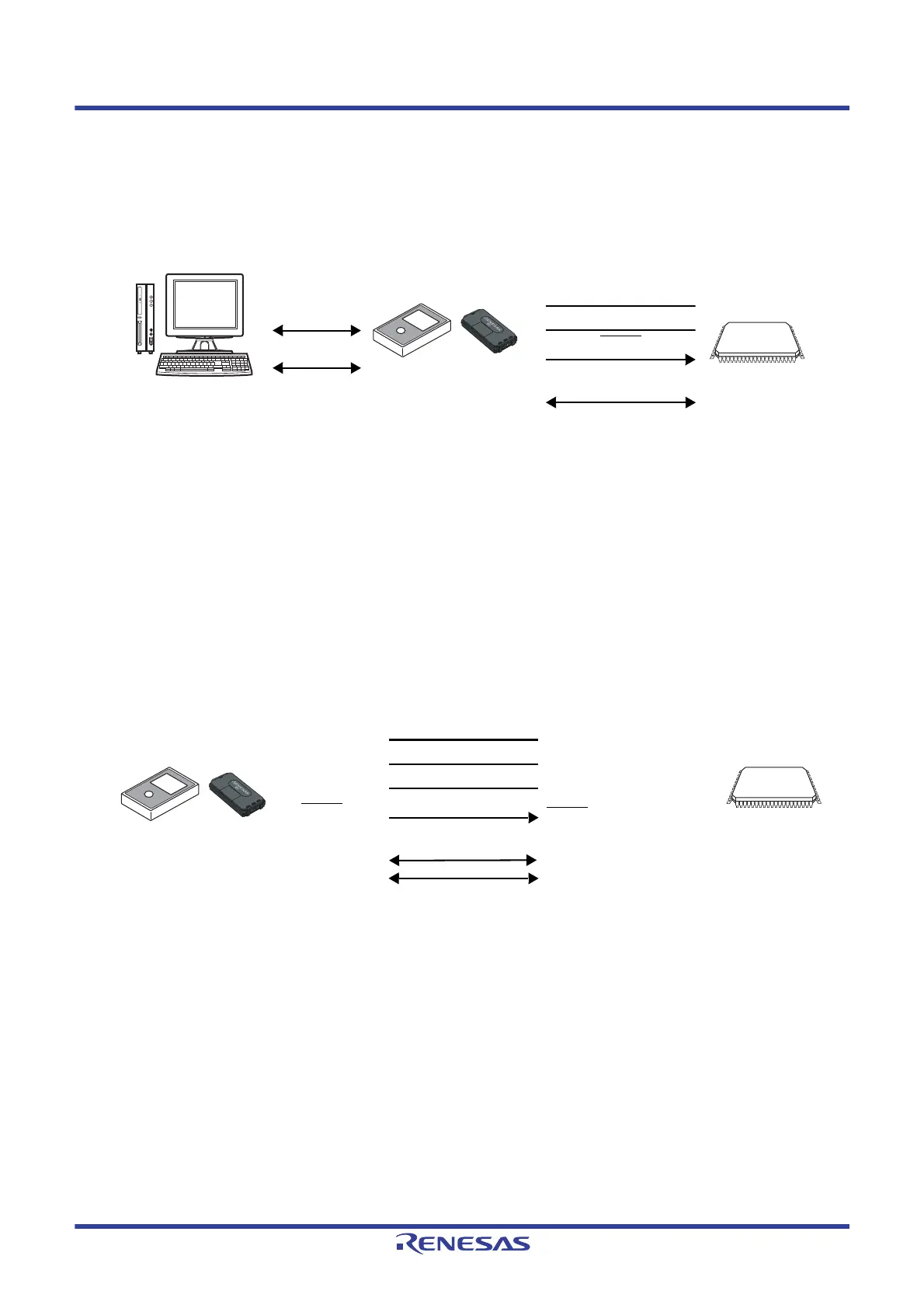
27.1.1 Programming Environment
The environment required for writing a program to the flash memory of the RL78 microcontroller is illustrated
below.
Figure 27 - 1 Environment for Writing Program to Flash Memory
A host machine that controls the dedicated flash memory programmer is necessary.
To interface between the dedicated flash memory programmer and the RL78 microcontroller, the TOOL0 pin is
used for manipulation such as writing and erasing via a dedicated single-line UART.
27.1.2 Communication Mode
Communication between the dedicated flash memory programmer and the RL78 microcontroller is established
by serial communication using the TOOL0 pin via a dedicated single-line UART of the RL78 microcontroller.
Transfer rate: 1 M, 500 k, 250 k, 115.2 kbps
Figure 27 - 2 Communication with Dedicated Flash Memory Programmer
Note 1. When using E1 on-chip debugging emulator.
Note 2. When using PG-FP5 or FL-PR5.
Note 3. Connect REGC pin to ground via a capacitor (0.47 to 1 μF).
TOOL0
(dedicated single-line UART)
RESET
VSS
VDD
Host machine
PG-FP5, FL-PR5 E1
RL78
microcontroller
Dedicated flash
memory programmer
RS-232C
USB
PG-FP5, FL-PR5 E1
Dedicated flash
memory programmer
VDD
EMVDD
Note 1
FLMD
Note 2
GND
RESET
Note 1
,
/RESET
Note 2
TOOL0
Note 1
,
SI/RxD
Note 2
VDD
VDD
VSS/REGC
Note 3
RESET
TOOL0
RL78
microcontroller
 Loading...


