RL78/G1H CHAPTER 5 PORT FUNCTIONS
R01UH0575EJ0120 Rev. 1.20 Page 72 of 920
Dec 22, 2016
5.2.12 Port 14
Port 14 is an I/O port with an output latch. Port 14 can be set to the input mode or output mode in 1-bit units using
port mode register 14 (PM14). When the P140 to P144 pins are used as an input port, use of an on-chip pull-up
resistor can be specified in 1-bit units by pull-up resistor option register 14 (PU14).
Input to the P142 and P143 pins can be specified through a normal input buffer or a TTL input buffer in 1-bit units
using port input mode register 14 (PIM14).
Output from the P142 to P144 pin can be specified as N-ch open-drain output (V
DD tolerance) in 1-bit units using
port output mode register 14 (POM14).
To use the P147 set it to digital I/O using port mode control register 14 (PMC14).
This port can also be used for clock/buzzer output, external interrupt request input, serial interface data I/O, and
clock I/O.
Reset signal generation sets port 14 to input port.
5.2.13 Port 15
Port 15 is an I/O port with an output latch. Port 15 can be set to the input mode or output mode in 1-bit units using
port mode register 15 (PM15).
This port can also be used for A/D converter analog input.
To use P155/ANI13 and P156/ANI14 as digital I/O pins, set them to digital I/O using the A/D port configuration
register (ADPC). Use these pins starting from the upper bit.
To use P155/ANI13 and P156/ANI14 as analog input pins, set them to analog function using the A/D port
configuration register (ADPC) and input mode using the PM15 register. Use these pins starting from the lower bit.
All P15 are set in the analog function mode when the reset signal is generated.
5.2.14 GPIO port
GPIO port is an I/O port with an output latch. For GPIO port, SCI20 enables the mode setting and I/O.
For details, see CHAPTER 18 RF TRANSCEIVER.
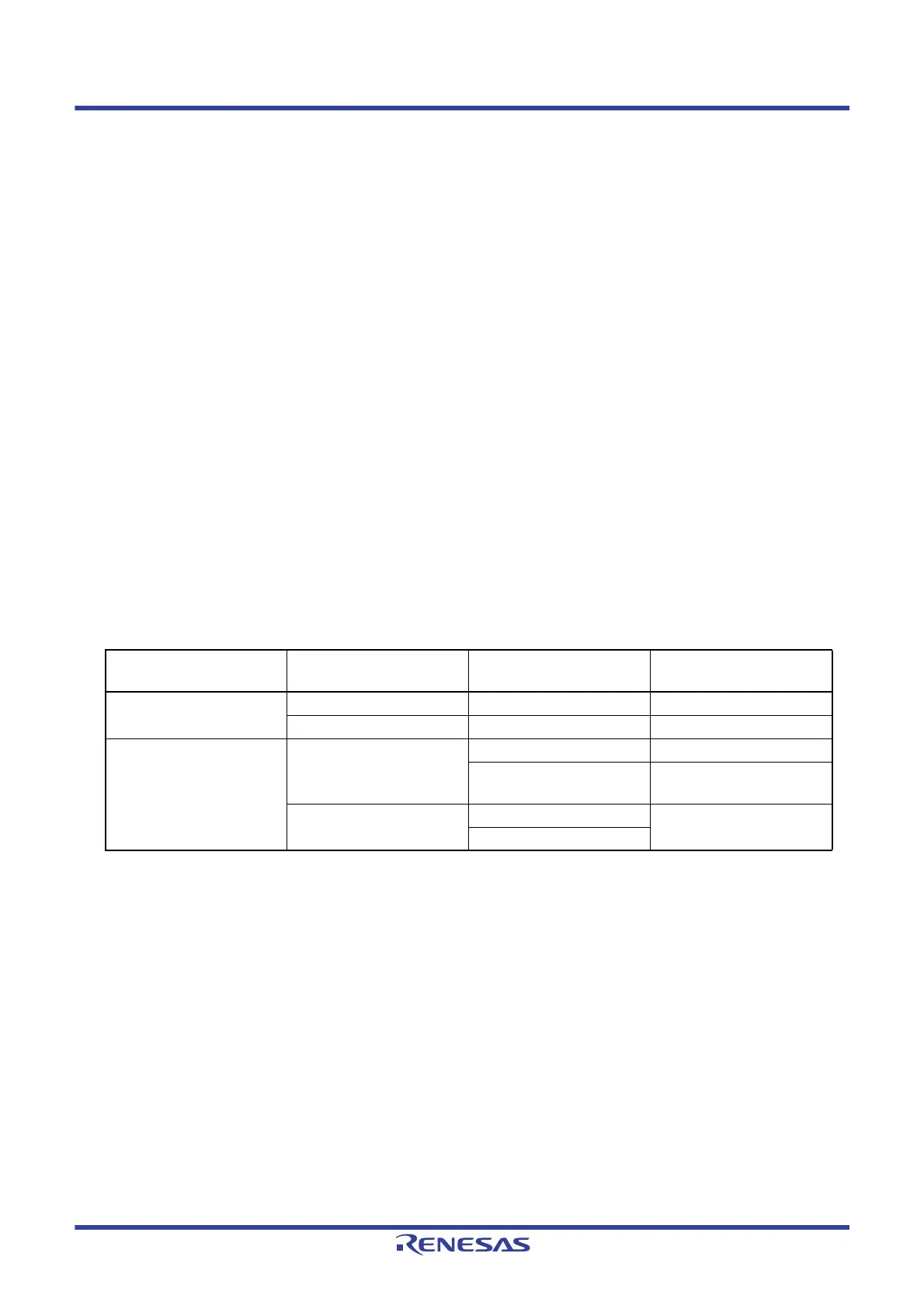
Table 5 - 3 Setting Functions of P155/ANI13 and P156/ANI14 Pins
ADPC Register PM15 Register ADS Register
P155/ANI13 and P156/ANI14
Pins
Digital I/O selection Input mode — Digital input
Output mode — Digital output
Analog function selection Input mode Selects ANI. Analog input (to be converted)
Does not select ANI. Analog input
(not to be converted)
Output mode Selects ANI. Setting prohibited
Does not select ANI.
 Loading...


