EasyManuals Logo

Renesas RL78/G1H User Manual

Renesas RL78/G1H
941 pages
To Next Page IconTo Next Page
To Previous Page IconTo Previous Page
Page #774 background imageLoading...
Page #774 background image
RL78/G1H CHAPTER 22 POWER-ON-RESET CIRCUIT
R01UH0575EJ0120 Rev. 1.20 Page 756 of 920
Dec 22, 2016
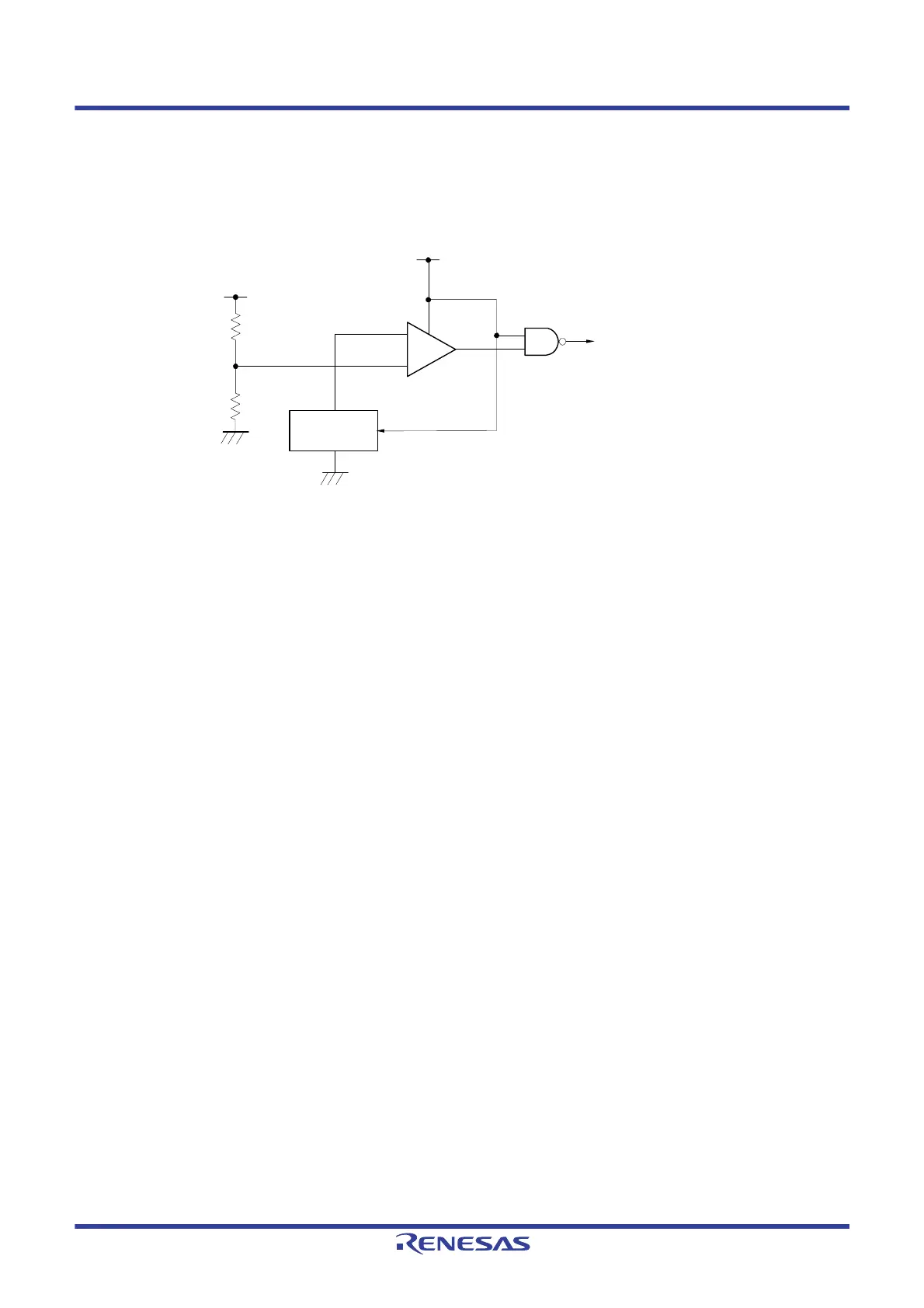
22.2 Configuration of Power-on-reset Circuit
The block diagram of the power-on-reset circuit is shown in Figure 22 - 1.
Figure 22 - 1 Block Diagram of Power-on-reset Circuit
22.3 Operation of Power-on-reset Circuit
The timing of generation of the internal reset signal by the power-on-reset circuit and voltage detector is shown next.
-
+
Reference
voltage source
Internal reset signal
VDD
VDD

Table of Contents

Questions and Answers:

Question and Answer IconNeed help?

Do you have a question about the Renesas RL78/G1H and is the answer not in the manual?

Renesas RL78/G1H Specifications

General IconGeneral
BrandRenesas
ModelRL78/G1H
CategoryMicrocontrollers
LanguageEnglish

Related product manuals