RL78/G1H CHAPTER 6 CLOCK GENERATOR
R01UH0575EJ0120 Rev. 1.20 Page 106 of 920
Dec 22, 2016
6.3.4 Oscillation stabilization time counter status register (OSTC)
This is the register that indicates the count status of the X1 clock oscillation stabilization time counter.
The X1 clock oscillation stabilization time can be checked in the following case,
• When the X1 clock starts oscillation while the high-speed on-chip oscillator clock or subsystem clock is being
used as the CPU clock.
• When the STOP mode is entered and then released while the high-speed on-chip oscillator clock is being used
as the CPU clock with the X1 clock oscillating.
The OSTC register can be read by a 1-bit or 8-bit memory manipulation instruction.
The generation of reset signal, the STOP instruction and MSTOP (bit 7 of clock operation status control register
(CSC)) = 1 clear the OSTC register to 00H.
Remark The oscillation stabilization time counter starts counting in the following cases.
• When oscillation of the X1 clock starts (EXCLK, OSCSEL = 0, 1 → MSTOP = 0)
• When the STOP mode is released
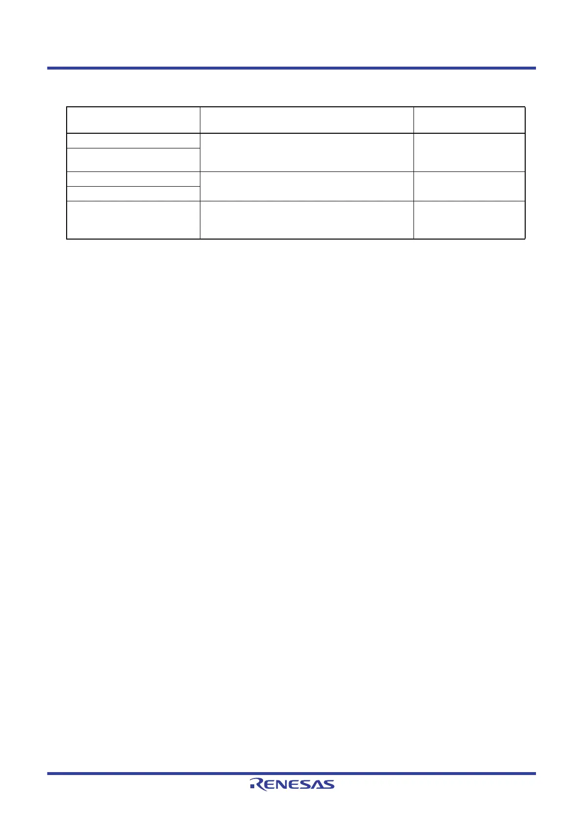
Table 6 - 2 Stopping Clock Method
Clock
Condition Before Stopping Clock
(Invalidating External Clock Input)
Setting of CSC Register Flags
X1 clock CPU and peripheral hardware clocks operate with a clock
other than the high-speed system clock.
(CLS = 0 and MCS = 0, or CLS = 1)
MSTOP = 1
External main system clock
XT1 clock CPU and peripheral hardware clocks operate with a clock
other than the subsystem clock. (CLS = 0)
XTSTOP = 1
External subsystem clock
High-speed on-chip oscillator clock CPU and peripheral hardware clocks operate with a clock
other than the high-speed on-chip oscillator clock.
(CLS = 0 and MCS = 1, or CLS = 1)
HIOSTOP = 1
 Loading...


