RL78/G1H CHAPTER 19 INTERRUPT FUNCTIONS
R01UH0575EJ0120 Rev. 1.20 Page 716 of 920
Dec 22, 2016
19.3.3 Priority specification flag registers (PR00L, PR00H, PR01L, PR01H,
PR02L, PR02H, PR10L, PR10H, PR11L, PR11H, PR12L, PR12H)
The priority specification flag registers are used to set the corresponding maskable interrupt priority level.
A priority level is set by using the PR0xy and PR1xy registers in combination (xy = 0L, 0H, 1L, 1H, 2L, or 2H).
The PR00L, PR00H, PR01L, PR01H, PR02L, PR02H, PR10L, PR10H, PR11L, PR11H, PR12L, and the PR12H
registers can be set by a 1-bit or 8-bit memory manipulation instruction. If the PR00L and PR00H registers, the
PR01L and PR01H registers, the PR02L and PR02H registers, the PR10L and PR10H registers, the PR11L and
PR11H registers, and the PR12L and PR12H registers are combined to form 16-bit registers PR00, PR01, PR02,
PR10, PR11, and PR12, they can be set by a 16-bit memory manipulation instruction.
Reset signal generation sets these registers to FFH.
Remark If an instruction that writes data to this register is executed, the number of instruction execution clocks
increases by 2 clocks.
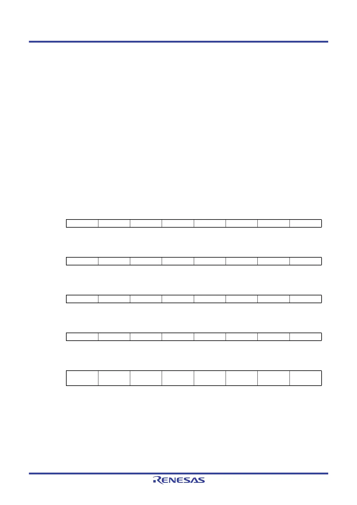
Figure 19 - 6 Format of Priority Specification Flag Registers (PR00L, PR00H, PR01L, PR01H, PR02L, PR02H,
PR10L, PR10H, PR11L, PR11H, PR12L, PR12H) (1/2)
Address: FFFE8H After reset: FFH R/W
Symbol 7 <6> <5> 4 3 <2> <1> <0>
PR00L 1 PPR04 PPR03 1 1 PPR00 LVIPR0 WDTIPR0
Address: FFFECH After reset: FFH R/W
Symbol 7 <6> <5> 4 3 <2> <1> <0>
PR10L 1 PPR14 PPR13 1 1 PPR10 LVIPR1 WDTIPR1
Address: FFFE9H After reset:FFH R/W
Symbol <7> 6 5 4 3 <2> <1> <0>
PR00H TMPR001H 1 1 1 1 TMPR011H CSIPR021 CSIPR020
Address: FFFEDH After reset: FFH R/W
Symbol <7> 6 5 4 3 <2> <1> <0>
PR10H TMPR101H 1 1 1 1 TMPR111H CSIPR121 CSIPR120
Address: FFFEAH After reset: FFH R/W
Symbol <7> <6> <5> <4> <3> <2> <1> <0>
PR01L TMPR003 TMPR002 TMPR001 TMPR000 IICAPR00
SREPR01
TMPR003H
SRPR01
STPR01
CSIPR010
 Loading...


