RL78/G1H CHAPTER 7 TIMER ARRAY UNIT
R01UH0575EJ0120 Rev. 1.20 Page 160 of 920
Dec 22, 2016
7.3.5 Timer channel enable status register m (TEm)
The TEm register is used to enable or stop the timer operation of each channel.
Each bit of the TEm register corresponds to each bit of the timer channel start register m (TSm) and the timer
channel stop register m (TTm). When a bit of the TSm register is set to 1, the corresponding bit of this register is
set to 1. When a bit of the TTm register is set to 1, the corresponding bit of this register is cleared to 0.
The TEm register can be read by a 16-bit memory manipulation instruction.
The lower 8 bits of the TEm register can be set with a 1-bit or 8-bit memory manipulation instruction with TEmL.
Reset signal generation clears this register to 0000H.
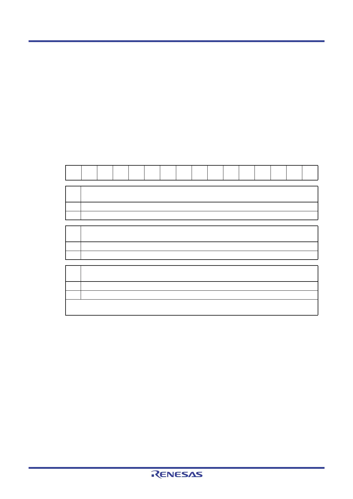
Figure 7 - 17 Format of Timer channel enable status register m (TEm)
Remark m: Unit number (m = 0, 1), n: Channel number (n = 0 to 3)
Address: F01B0H, F01B1H (TE0), F01F0H, F01F1H (TE1) After reset: 0000H R
Symbol1514131211109876543210
TEm0000
TEHm
3
0
TEHm
1
00000TEm3TEm2TEm1TEm0
TEH
m3
Indication of whether operation of the higher 8-bit timer is enabled or stopped when channel 3 is in the 8-bit
timer mode
0 Operation is stopped.
1 Operation is enabled.
TEH
m1
Indication of whether operation of the higher 8-bit timer is enabled or stopped when channel 1 is in the 8-bit
timer mode
0 Operation is stopped.
1 Operation is enabled.
TEm
n
Indication of operation enable/stop status of channel n
0 Operation is stopped.
1 Operation is enabled.
This bit displays whether operation of the lower 8-bit timer for TEm1 and TEm3 is enabled or stopped when channel 1
or 3 is in the 8-bit timer mode.
 Loading...


