RL78/G1H CHAPTER 13 A/D CONVERTER
R01UH0575EJ0120 Rev. 1.20 Page 299 of 920
Dec 22, 2016
13.3.7 Analog input channel specification register (ADS)
This register specifies the input channel of the analog voltage to be A/D converted.
The ADS register can be set by a 1-bit or 8-bit memory manipulation instruction.
Reset signal generation clears this register to 00H.
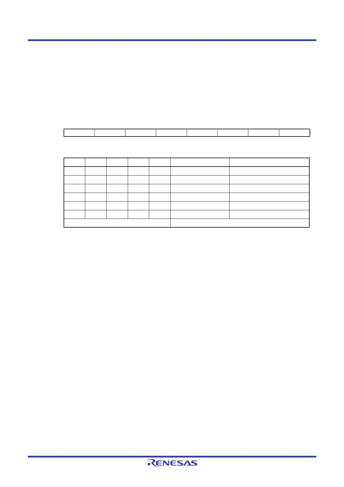
Figure 13 - 12 Format of Analog input channel specification register (ADS)
• Select mode (ADMD = 0)
Caution 1. Be sure to clear bits 5, 6, and 7 to 0.
Caution 2. Set a channel to be set the analog input by ADPC and PMCx registers in the input mode by using port
mode registers 2, 12, and 15 (PM2, PM12, PM15).
Caution 3. Do not set the pin that is set by the A/D port configuration register (ADPC) as digital I/O by the ADS
register.
Caution 4. Do not set the pin that is set by Port mode control register 12 (PMC12) as digital I/O by the ADS
register.
Caution 5. If using AV
REFP as the + side reference voltage of the A/D converter, do not select ANI0 as an A/D
conversion channel.
Caution 6. If using AV
REFM as the − side reference voltage of the A/D converter, do not select ANI1 as an A/D
conversion channel.
Address: FFF31H After reset: 00H R/W
Symbol76543210
ADS 0 0 0 ADS4 ADS3 ADS2 ADS1 ADS0
ADS4 ADS3 ADS2 ADS1 ADS0 Analog input channel Input source
00000 ANI0 P20/ANI0/AV
REFP pin
00001 ANI1 P21/ANI1/AV
REFM pin
00010 ANI2 P22/ANI2 pin
01101 ANI13 P155/ANI13 pin
01110 ANI14 P156/ANI14 pin
10011 ANI19 P120/ANI19 pin
Other than the above Setting prohibited
 Loading...


