RL78/G1H CHAPTER 31 ELECTRICAL SPECIFICATIONS
R01UH0575EJ0120 Rev. 1.20 Page 908 of 920
Dec 22, 2016
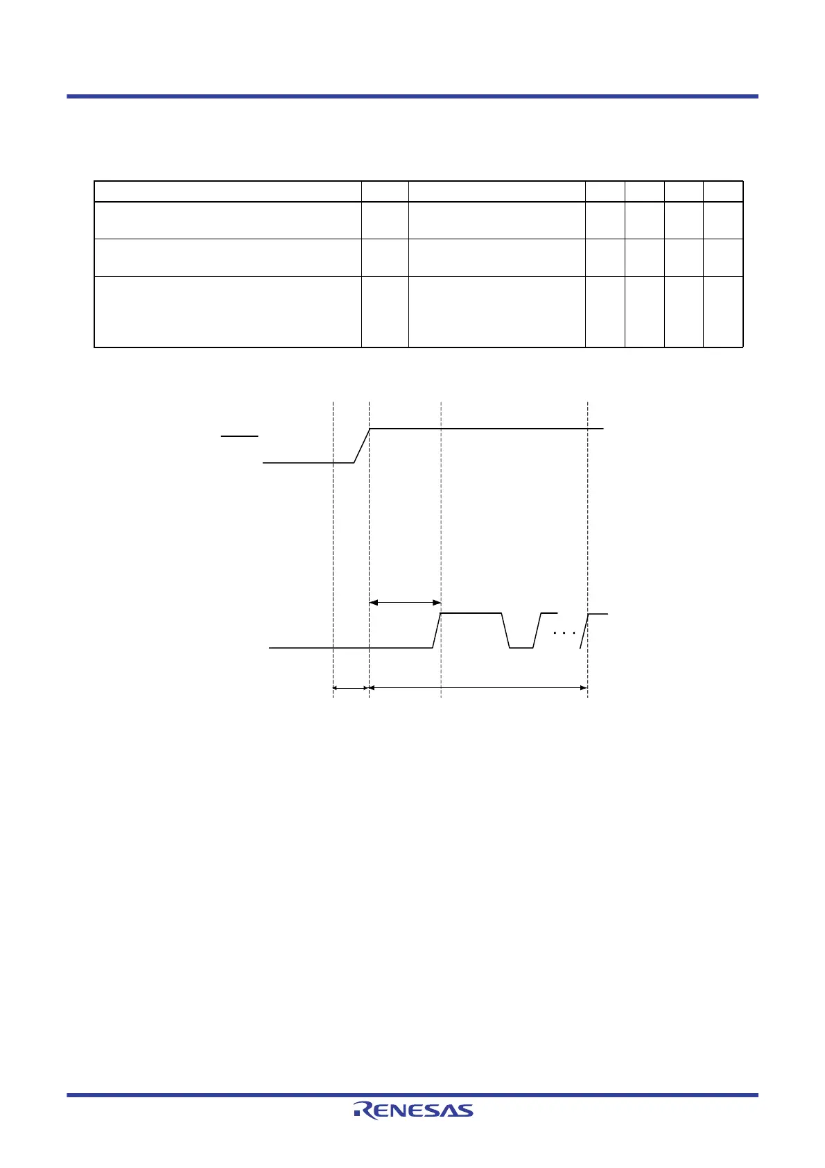
31.11 Timing for Switching Flash Memory Programming Modes
<1> The low level is input to the TOOL0 pin.
<2> The external reset ends (POR and LVD reset must end before the external reset ends).
<3> The TOOL0 pin is set to the high level.
<4> The baud rate setting by UART reception is completed.
Remark tSUINIT: The segment shows that it is necessary to finish specifying the initial communication settings within 100 ms from
when the external resets end.
t
SU: How long from when the TOOL0 pin is placed at the low level until a pin reset ends.
t
HD: How long to keep the TOOL0 pin at the low level from when the external resets end.
(excluding the processing time of the firmware to control the flash memory)
(TA = ‒40 to +85 °C, 1.8 V ≤ VDD ≤ 3.6 V, VSS = 0 V)
Parameter Symbol Conditions MIN. TYP. MAX. Unit
How long from when an external reset ends until the
initial communication settings are specified
t
SUINIT POR and LVD reset must end
before the external reset ends.
100 ms
How long from when the TOOL0 pin is placed at the
low level until an external reset ends
t
SU POR and LVD reset must end
before the external reset ends.
10 μs
How long the TOOL0 pin must be kept at the low
level after an external reset ends
(excluding the processing time of the firmware to
control the flash memory)
t
HD POR and LVD reset must end
before the external reset ends.
1ms
TOOL0
<1> <2> <3>
tSU
<4>
t
SUINIT
723 µs + tHD
processing
time
00H reception
(TOOLRxD, TOOLTxD mode)
RESET
 Loading...


