RL78/G1H CHAPTER 19 INTERRUPT FUNCTIONS
R01UH0575EJ0120 Rev. 1.20 Page 718 of 920
Dec 22, 2016
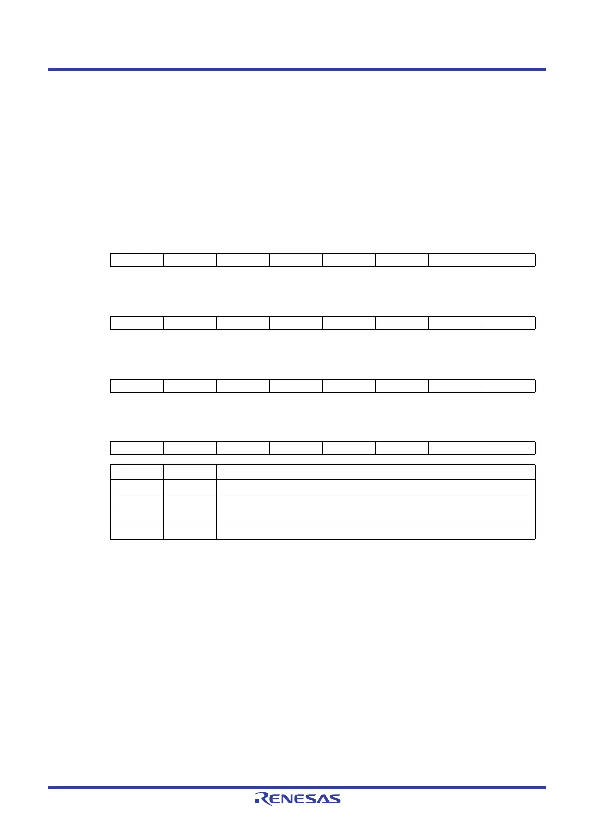
19.3.4 External interrupt rising edge enable registers (EGP0, EGP1), external
interrupt falling edge enable registers (EGN0, EGN1)
These registers specify the valid edge for INTPn pin.
The EGP0, EGP1, EGN0, and EGN1 registers can be set by a 1-bit or 8-bit memory manipulation instruction.
Reset signal generation clears these registers to 00H.
Figure 19 - 8 Format of External Interrupt Rising Edge Enable Registers (EGP0, EGP1) and External Interrupt
Falling Edge Enable Registers (EGN0, EGN1)
Address: FFF38H After reset: 00H R/W
Symbol76543210
EGP0 EGP7 EGP6 0 EGP4 EGP3 0 0 EGP0
Address: FFF39H After reset: 00H R/W
Symbol76543210
EGN0 EGN7 EGN6 0 EGN4 EGN3 0 0 EGN0
Address: FFF3AH After reset: 00H R/W
Symbol76543210
EGP1 0 0 0 0 EGP11 EGP10 EGP9 0
Address: FFF3BH After reset: 00H R/W
Symbol76543210
EGN1 0 0 0 0 EGN11 EGN10 EGN9 0
EGPn EGNn INTPn pin valid edge selection (n = 0 to 11)
0 0 Edge detection disabled
0 1 Falling edge
1 0 Rising edge
1 1 Both rising and falling edges
 Loading...


