RL78/G1H CHAPTER 9 REAL-TIME CLOCK
R01UH0575EJ0120 Rev. 1.20 Page 241 of 920
Dec 22, 2016
9.3.3 Real-time clock control register 0 (RTCC0)
The RTCC0 register is an 8-bit register that is used to start or stop the real-time clock operation, and set a 12- or
24-hour system and the constant-period interrupt function.
The RTCC0 register can be set by a 1-bit or 8-bit memory manipulation instruction.
Reset signal generation clears this register to 00H.
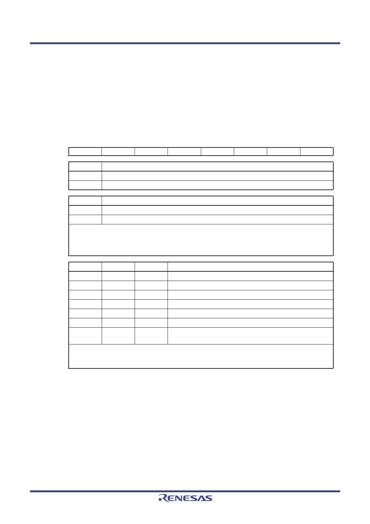
Figure 9 - 4 Format of Real-time clock control register 0 (RTCC0)
Remark ×: Don’t care
Address: FFF9DH After reset: 00H R/W
Symbol<7>6543210
RTCC0 RTCE 0 0 0 AMPM CT2 CT1 CT0
RTCE Real-time clock operation control
0 Stops counter operation.
1 Starts counter operation.
AMPM Selection of 12-/24-hour system
0 12-hour system (a.m. and p.m. are displayed.)
1 24-hour system
• Rewrite the AMPM bit value after setting the RWAIT bit (bit 0 of real-time clock control register 1 (RTCC1)) to 1. If the
AMPM bit value is changed, the values of the hour count register (HOUR) change according to the specified time
system.
• Table 9 - 2 shows the Displayed Time Digits.
CT2 CT1 CT0 Constant-period interrupt (INTRTC) selection
0 0 0 Does not use fixed-cycle interrupt function.
0 0 1 Once per 0.5 s (synchronized with second count up)
0 1 0 Once per 1 s (same time as second count up)
0 1 1 Once per 1 m (second 00 of every minute)
1 0 0 Once per 1 hour (minute 00 and second 00 of every hour)
1 0 1 Once per 1 day (hour 00, minute 00, and second 00 of every day)
11
× Once per 1 month (Day 1, hour 00 a.m., minute 00, and second 00 of
every month)
When changing the values of the CT2 to CT0 bits while the counter operates (RTCE = 1), rewrite the values of the CT2
to CT0 bits after disabling interrupt servicing INTRTC by using the interrupt mask flag register. Furthermore, after
rewriting the values of the CT2 to CT0 bits, enable interrupt servicing after clearing the RIFG and RTCIF flags.
 Loading...


