RL78/G1H CHAPTER 23 VOLTAGE DETECTOR
R01UH0575EJ0120 Rev. 1.20 Page 761 of 920
Dec 22, 2016
23.2 Configuration of Voltage Detector
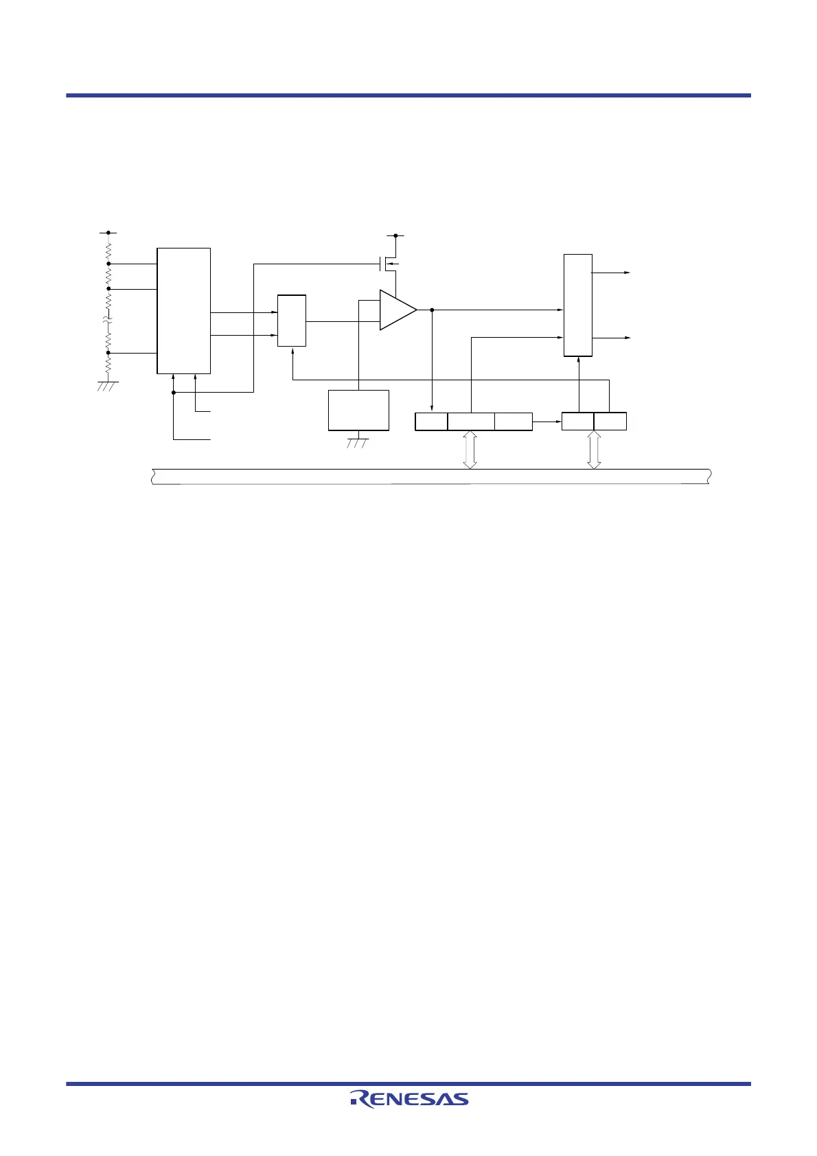
The block diagram of the voltage detector is shown in Figure 23 - 1.
Figure 23 - 1 Block Diagram of Voltage Detector
23.3 Registers Controlling Voltage Detector
The voltage detector is controlled by the following registers.
• Voltage detection register (LVIM)
• Voltage detection level register (LVIS)
LVIOMSK
-
+
Reference
voltage
source
Internal bus
Voltage detection
register (LVIM)
INTLVI
Internal reset signal
VDD
VLVDH
VLVDL/
V
LVD
VDD
N-ch
LVILV
LVIMD
LVIF
Option byte (000C1H)
LVIS1, LVIS0
Option byte (000C1H)
VPOC2 to VPOC0
Voltage detection
level register (LVIS)
LVISEN
Controller
Selector
Voltage detection
level selector
 Loading...


