RL78/G1H CHAPTER 15 SERIAL INTERFACE IICA
R01UH0575EJ0120 Rev. 1.20 Page 443 of 920
Dec 22, 2016
15.3.5 IICA control register n1 (IICCTLn1)
This register is used to set the operation mode of I
2
C and detect the statuses of the SCLAn and SDAAn pins.
The IICCTLn1 register can be set by a 1-bit or 8-bit memory manipulation instruction. However, the CLDn and
DADn bits are read-only.
Set the IICCTLn1 register, except the WUPn bit, while operation of I
2
C is disabled (bit 7 (IICEn) of IICA control
register n0 (IICCTLn0) is 0).
Reset signal generation clears this register to 00H.
Figure 15 - 14 Format of IICA control register n1 (IICCTLn1) (1/2)
Note 1. Bits 4 and 5 are read-only.
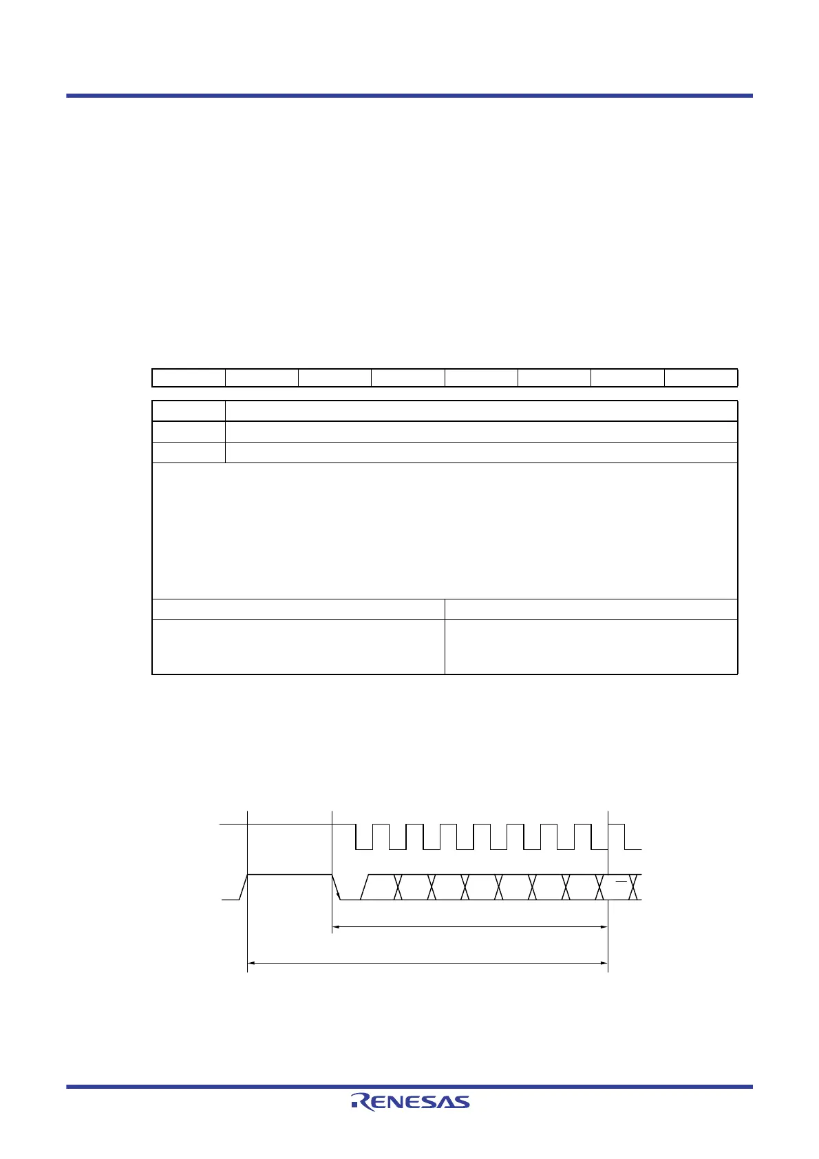
Note 2. The status of the IICA status register n (IICSn) must be checked and the WUPn bit must be set during the
period shown below.
Remark n = 0, 1
Address: F0231H (IICCTL01), F0239H (IICCTL11) After reset: 00H R/W
Note 1
Symbol <7> 6 <5> <4> <3> <2> 1 <0>
IICCTLn1 WUPn 0 CLDn DADn SMCn DFCn 0 PRSn
WUPn Control of address match wakeup
0 Stops operation of address match wakeup function in STOP mode.
1 Enables operation of address match wakeup function in STOP mode.
To shift to STOP mode when WUPn = 1, execute the STOP instruction at least three f
MCK clocks after setting (1) the
WUPn bit (see
Figure 15 - 28 Flow When Setting WUPn = 1).
Clear (0) the WUPn bit after the address has matched or an extension code has been received. The subsequent
communication can be entered by the clearing (0) WUPn bit. (The wait must be released and transmit data must be
written after the WUPn bit has been cleared (0).)
The interrupt timing when the address has matched or when an extension code has been received, while WUPn = 1, is
identical to the interrupt timing when WUPn = 0. (A delay of the difference of sampling by the clock will occur.)
Furthermore, when WUPn = 1, a stop condition interrupt is not generated even if the SPIEn bit is set to 1.
Condition for clearing (WUPn = 0) Condition for setting (WUPn = 1)
• Cleared by instruction (after address match or extension
code reception)
• Set by instruction (when the MSTSn, EXCn, and COIn
bits are “0”, and the STDn bit also “0” (communication
not entered))
Note 2
SCLAn
<1> <2>
SDAAn
A6
The maximum time from reading IICSn to setting
WUPn is the period from <1> to <2>.
Check the IICSn operation status and set WUPn during this period.
A5 A4 A3 A2 A1 A0 R/W
 Loading...


