RL78/G1H CHAPTER 18 RF TRANSCEIVER
R01UH0575EJ0120 Rev. 1.20 Page 601 of 920
Dec 22, 2016
(33) ACK counter compare registers 0 and 1 (ACKCOMP0, ACKCOMP1)
These registers are used to set each of the timings upon automatic ACK reply mode.
The ACKCOMP0 and ACKCOMP1 registers consist of 16 bits and can be accessed (serial interface
communication) in 8 bit unit.
Reset signal generation sets ACKCOMP0 to 0014H and sets ACKCOMP1 to 000EH.
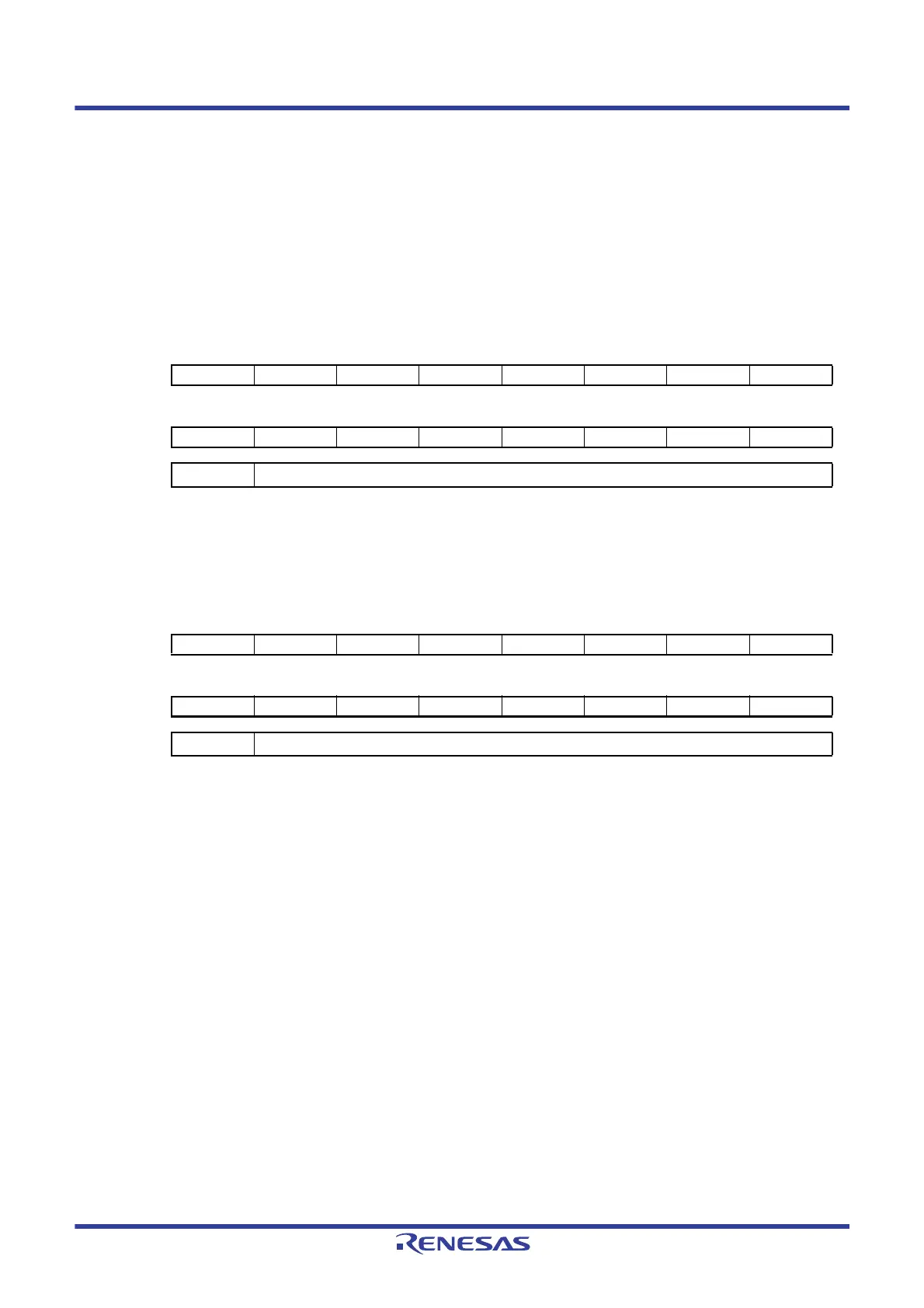
Figure 18 - 42 ACK Counter Compare Register 0 (ACKCOMP0) Format
Figure 18 - 43 ACK Counter Compare Register 1 (ACKCOMP1) Format
Address:
0041H, 0040H
After reset:
0014H
R/W
Symbol 15 14 13 12 11 10 9 8
ACKCOM
P0
76543210
ACKCOMP0 ACK counter compare 0 value
Address:
0043H, 0042H
After reset:
000EH
R/W
Symbol 15 14 13 12 11 10 9 8
ACKCOM
P1
76543210
ACKCOMP1 ACK counter compare 1 value
 Loading...


