4.9
Date Code 20100129 Instruction Manual SEL-751A Relay
Protection and Logic Functions
Basic Protection
When a core-balance CT is not available, use the 50G residual overcurrent
elements.
.
The relay offers four negative-sequence overcurrent elements to detect phase-
to-phase faults, phase reversal, single phasing, and unbalance load.
Time-Overcurrent
Elements
One level of inverse time element is available for phase A, B, C, and negative-
sequence overcurrent. Also, two levels of inverse time elements are available
for maximum phase, neutral, and residual overcurrent. See Table 4.8 through
Table 4.12 for available settings.
You can select from five U.S. and five IEC inverse characteristics. Table 4.13
and Table 4.1 4 show equations for the curves and Figure 4.8 through
Figure 4.17 show the curves. The curves and equations shown do not account
for constant time adder and minimum response time (settings 51_CT and
51_MR respectively, each assumed equal to zero). Use the 51_CT if you want
to raise the curves by a constant time. Also, you can use the 51_MR if you
want to ensure the curve times no faster than a minimum response time.
RES OC TRIP DLY 0.00–5.00 sec 50G4D := 0.50
RES OC TRQ CON SELOGIC 50G4TC := 1
a
For I
NOM
= 5 A.
b
For I
NOM
= 1 A.
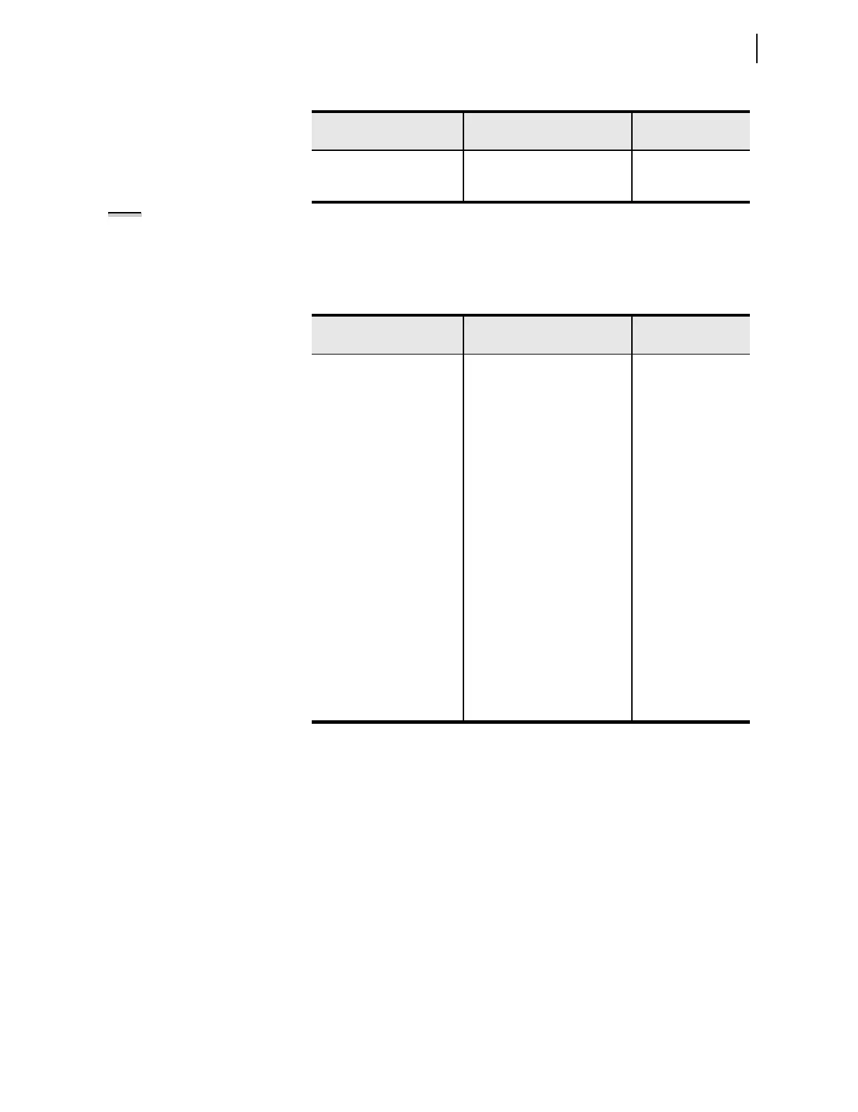
Table 4.7 Negative-Sequence Overcurrent Settings
Setting Prompt Setting Range
Setting Name :=
Factory Defau lt
NSEQ OC TRIP LVL OFF, 0.50–100.00 A
a
,
0.10–20.00 A
b
a
For I
NOM
= 5 A.
b
For I
NOM
= 1 A.
50Q1P := OFF
NSEQ OC TRIP DLY 0.1–120.0 sec 50Q1D := 0.2
NSEQ OC TRQ CON SEL
OGIC 50Q1TC := 1
NSEQ OC TRIP LVL OFF, 0.50–100.00 A
a
,
0.10–20.00 A
b
50Q2P := OFF
NSEQ OC TRIP DLY 0.1–120.0 sec 50Q2D := 0.2
NSEQ OC TRQ CON SEL
OGIC 50Q2TC := 1
NSEQ OC TRIP LVL OFF, 0.50–100.00 A
a
,
0.10–20.00 A
b
50Q3P := OFF
NSEQ OC TRIP DLY 0.1–120.0 sec 50Q3D := 0.2
NSEQ OC TRQ CON SEL
OGIC 50Q3TC := 1
NSEQ OC TRIP LVL OFF, 0.50–100.00 A
a
,
0.10–20.00 A
b
50Q4P := OFF
NSEQ OC TRIP DLY 0.1–120.0 sec 50Q4D := 0.2
NSEQ OC TRQ CON SELOGIC 50Q4TC := 1
Table 4.6 Residual Overcurrent Settings (Sheet 2 of 2)
Setting Prompt Setting Range
Setting Name :=
Factory Defau lt
NOTE: Phase CT ratios are typically
higher than core-balance (CB) CT
ratios. For this reason, the relay
sensitivity to ground faults is less
when the residual overcurrent
element is used instead of the CB
element. A separate ground fault
detection method should be used if a
CB CT is not available in applications
where resistance grounding reduces
the available ground fault current.