5.19
Date Code 20100129 Instruction Manual SEL-751A Relay
Metering and Monitoring
Breaker Monitor
In Figure 5.18, note that the breaker maintenance curve levels off horizontally
above set point KASP1, COSP1. This is the close/open operation limit of the
circuit breaker (COSP1 = 10000), regardless of interrupted current value.
Also, note that the breaker maintenance curve falls vertically below set point
KASP3, COSP3. This is the maximum interrupted current limit of the circuit
breaker (KASP3 = 20.0 kA). If the interrupted current is greater than setting
KASP3, the interrupted current is accumulated as a current value equal to
setting KASP3.
Operation of SELOGIC Control Equation Breaker Monitor Initiation Setting
BKMON
The SELOGIC control equation breaker monitor initiation setting BKMON in
Table 5.10 determines when the breaker monitor reads in current values
(Phases A, B, and C) for the breaker maintenance curve (see Figure 5.18) and
the breaker monitor accumulated currents/trips [see BRE Command (Breaker
Monitor Data) on page 7.21].
The BKMON setting looks for a rising edge (logical 0 to logical 1 transition)
as the indication to read in current values. The acquired current values are then
applied to the breaker maintenance curve and the breaker monitor
accumulated currents/trips (see references in previous paragraph).
In the factory default settings, the SEL
OGIC control equation breaker monitor
initiation setting is set:
BKMON = TRIP (TRIP is the logic output of Figure 4.29)
Refer to Figure 5.19. When BKMON asserts (Relay Word bit TRIP goes from
logical 0 to logical 1), the breaker monitor reads in the current values and
applies them to the breaker monitor maintenance curve and the breaker
monitor accumulated currents/trips.
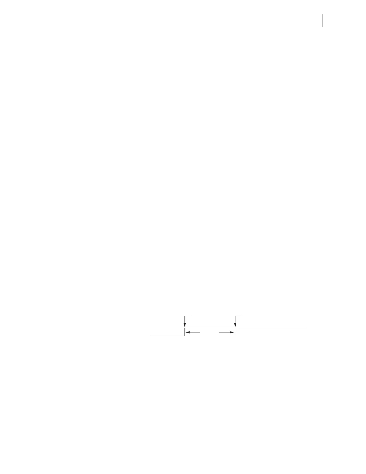
As detailed in Figure 5.19, the breaker monitor actually reads in the current
values 1.5 cycles after the assertion of BKMON. This helps especially if an
instantaneous trip occurs. The instantaneous element trips when the fault
current reaches its pickup setting level. The fault current may still be
“climbing” to its full value, at which it levels off. The 1.5-cycle delay on
reading in the current values allows time for the fault current to level off.
Figure 5.19 Operation of SELOGIC Control Equation Breaker Monitor
Initiation Setting
See Figure 5.24 and accompanying text for more information on setting
BKMON. The operation of the breaker monitor maintenance curve, when new
current values are read in, is explained in the following example.
Breaker Monitor
Operation Example
As stated earlier, each phase (A, B, and C) has its own breaker maintenance
curve. For this example, presume that the interrupted current values occur on a
single phase in Figure 5.20–Figure 5.23. Also, presume that the circuit
breaker interrupting contacts have no wear at first (brand new or recent
maintenance performed).
Read in
Current Values
BKMON
1.5 Cycle
Rising
Edge