2.31
Date Code 20100129 Instruction Manual SEL-751A Relay
Installation
Arc-Flash Protection: System Installation
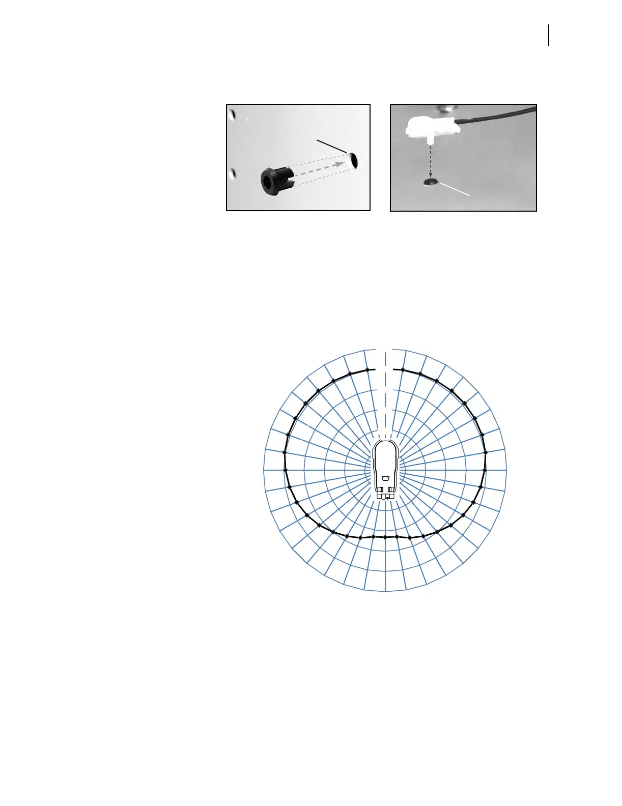
The sensor is mounted flush on the switchgear cabinet wall, using a standard
1/4-inch hole. Mounting steps are shown in Figure 2.29.
Figure 2.29 Point-Sensor Installation
The point sensor is omnidirectional with a slight loss of sensitivity at the fiber
entry point. Figure 2.30, Figure 2.31, and Figure 2.32 show the sensor
directivity pattern. The point sensor must be located in clear view of energized
parts, which are most likely to cause an arc-flash event.
Figure 2.30 Point-Sensor Directivity (0–360° Around the Mounting Plane)
1. Mounting Grommet Insertion
(1/4” diameter hole)
2. Sensor Insertion
(1/4” diameter hole)
120%
100%
80%
60%
40%
20%
0%
0°
350° 10°
340° 20°
330° 30°
320° 40°
310° 50°
300° 60°
290° 70°
280° 80°
270° 90°
260° 100°
250° 110°
240° 120°
230° 130°
220° 140°
210° 150°
200° 160°
190° 170°
180°